CCNP ROUTE 300-101 Part 3.13 – Identify Suboptimal Routing

Suboptimal Routing

When multiple routers redistribute between the same two routing protocol domains,
several potential problems can occur. One type of problem occurs on the redistributing
routers, because those routers will learn a route to most subnets through both routing
protocols. That router uses the AD to determine the best route when comparing the best
routes from each of the two routing protocols, this typically results in some routes using
suboptimal paths.

Initially you should avoid any kind of redistribution but if that is not possible, you must be careful and remember that routing protocols by default will choose routes based on administrative distance or metrics.

To solve this type of problem, the redistributing routers must have some awareness of
which routes came from the other routing domain. The lower AD routing protocol needs to decide which routes came from the higher AD routing protocol, and either use a different AD for those routes or filter the routes. Though there are a few different methods of preventing this type of problem.


Mutual Redistribution at Multiple Routers

When multiple routers redistribute between the same two routing protocol domains,
several potential problems can occur. One type of problem occurs on the redistributing
routers, because those routers will learn a route to most subnets through both routing
protocols. That router uses the AD to determine the best route when comparing the best
routes from each of the two routing protocols; this typically results in some routes using
suboptimal paths.

Below shows a sample network, with R3 choosing its AD 110 OSPF route to 10.1.2.0/24 network over the probably better route but with AD 120 RIP route (only 1 hop away).

Mutual Redistribution Suboptimal Routing


R3 learns of subnet 10.1.2.0/24 through RIP updates from R2. Also, R1 learns of the subnet with RIP and redistributes the route into OSPF, and then R3 learns of a route to 10.1.2.0/24 through OSPF. R3 chooses the route with the lower administrative distance, with all default settings, OSPF’s AD of 110 is better that RIP’s 120.

If both R1 and R3 mutually redistribute between RIP and OSPF, the suboptimal route
problem would occur on either R1 or R3 for each RIP subnet, all depending on timing.

Below example shows the redistribution configuration, along with R3 having the suboptimal route shown in the above topology. However, after R1’s fa0/0 interface flaps, R1 now has a suboptimal route to 10.1.2.0/24, but R3 has an optimal route.

! R1's related configuration follows:
router ospf 1
router-id 1.1.1.1
redistribute rip subnets
network 10.1.15.1 0.0.0.0 area 0
!
router rip
redistribute ospf 1
network 10.0.0.0
default-metric 1

! R3's related configuration follows:
router ospf 1
router-id 3.3.3.3
redistribute rip subnets
network 10.1.34.3 0.0.0.0 area 0
!
router rip
redistribute ospf 1
network 10.0.0.0
default-metric 1

! R3 begins with an AD 110 OSPF route, and not a RIP route, to 10.1.2.0/24.
R3# sh ip route | incl 10.1.2.0
O E2 10.1.2.0 [110/20] via 10.1.34.4, 00:02:01, Serial0/0/0.4

! R1 has a RIP route to 10.1.2.0/24, and redistributes it into OSPF, causing R3
! to learn an OSPF route to 10.1.2.0/24.
R1# sh ip route | incl 10.1.2.0
R 10.1.2.0 [120/1] via 10.1.12.2, 00:00:08, FastEthernet0/0

! Next, R1 loses its RIP route to 10.1.2.0/24, causing R3 to lose its OSPF route.
R1# conf t
Enter configuration commands, one per line. End with CNTL/Z.
R1(config)# int fa 0/0
R1(config-if)# shut

! R3 loses its OSPF route, but can then insert the RIP route into its table.
R3# sh ip route | incl 10.1.2.0
R 10.1.2.0 [120/1] via 10.1.23.2, 00:00:12, Serial0/0/0.2

! Not shown: R1 brings up its fa0/0 again
! However, R1 now has the suboptimal route to 10.1.2.0/24, through OSPF.
R1# sh ip route | incl 10.1.2.0
O E2 10.1.2.0 [110/20] via 10.1.15.5, 00:00:09, Serial0/0/0.5


The key concept behind this seemingly odd example is that a redistributing router processes only the current contents of its IP routing table. When this network first came up, R1 learned its RIP route to 10.1.2.0/24, and redistributed into OSPF, before R3 could do
the same. So, R3 was faced with the choice of putting the AD 110 (OSPF) or AD 120 (RIP) route into its routing table, and R3 chose the lower AD OSPF route. Because R3 never had the RIP route to 10.1.2.0/24 in its routing table, R3 could not redistribute that RIP route into OSPF.

Later, when R1’s fa0/0 failed, R3 had time to remove the OSPF route and add the RIP route for 10.1.2.0/24 to its routing table—which then allowed R3 to redistribute that RIP route into OSPF, causing R1 to have the suboptimal route.


Preventing Suboptimal Routes by Setting the Administrative Distance

A simple and elegant solution to the problem of suboptimal routes on redistributing routers is to flag the redistributed routes with a higher AD.

A route’s AD is not advertised by the routing protocol. However, a single router can be configured such that it assigns different AD values to different routes, which then impacts that one router’s choice of which routes end up in the routing table.

For the above example, R3 could have assigned the OSPF-learned route to 10.1.2.0/24, an AD higher than 120, thereby preventing the original problem.

Below shows a more complete example, with a route from the RIP domain (10.1.2.0/24) and another from the OSPF domain (10.1.4.0/24). Redistributing Router R3 will learn the two routes both from RIP and OSPF. When you configure R3’s logic to treat OSPF internal routes with default AD 110, and OSPF external routes with AD 180 (or any other value larger than RIP’s default of 120), R3 will choose the optimal path for both RIP and OSPF routes.

Effect of Differing ADs for Internal and External Routes


Both R1’s and R3’s configurations look like the previous example, but with the addition of the distance command.

R3(config)# router ospf 1
R3(config-router)# distance ospf external 180


R3 has a more optimal RIP route to 10.1.2.0/24, as does R1.

R3# sh ip route | incl 10.1.2.0
R 10.1.2.0 [120/1] via 10.1.23.2, 00:00:19, Serial0/0/0.2


On R1 as the following

R1# show ip route | incl 10.1.2.0_
R 10.1.2.0 [120/1] via 10.1.12.2, 00:00:11, FastEthernet0/0


R1 loses its next-hop interface for the RIP route, so now its OSPF route, with AD 180, is its only and best route to 10.1.2.0/24.

R1# conf t
Enter configuration commands, one per line. End with CNTL/Z.
R1(config)# int fa 0/0
R1(config-if)# shut
R1(config-if)# do sh ip route | incl 10.1.2.0
O E2 10.1.2.0 [180/20] via 10.1.15.5, 00:00:05, Serial0/0/0.5


EIGRP supports the exact same concept by default, using AD 170 for external routes and 90 for internal routes. In fact, if EIGRP were used instead of OSPF, neither R1 nor R3 would have experienced any of the suboptimal routing. You can reset EIGRP’s distance for internal and external routes by using the distance eigrp value router subcommand.

In some cases, the requirements might not allow for setting all external routes’ ADs to
another value. Example, if R4 injected some legitimate external routes into OSPF, the
configuration would result in either R1 or R3 having a suboptimal route to those external routes that pointed through the RIP domain. In those cases, the distance router subcommand can be used in a different way, influencing some of or all the routes that come from a particular router. The syntax is as follows:

 distance {distance-value ip-address {wildcard-mask} [ip-standard-list] [ip-extended-list]


This command sets three key pieces of information: the AD to be set, the IP address of
the router advertising the routes, and optionally, an ACL with which to match routes.

With RIP, and EIGRP, this command identifies a neighboring router’s interface address using the ip-address wildcard-mask parameters.

With OSPF, those same parameters identify the RID of the router owning (creating) the link-state advertisement (LSA) for the route. The optional ACL then identifies the subset of routes for which the AD will be set. The logic boils down to something like this:

Set this AD value for all routes, learned from a router that is defined by the IP address and wildcard mask, and for which the ACL permits the route.

Below shows how the command could be used to solve the same suboptimal route problem on R1 and R3, while not causing suboptimal routing for other external routes. The design goals are summarized as follows:

  • Set a router’s local AD for its OSPF routes for subnets in the RIP domain to a value of 179, thereby making the RIP routes to those subnets better than the OSPF routes to those same subnets.
  • Do not set the AD for any other routes.


Using the distance command to reset particular routes’ ADs

Note that the command refers to 3.3.3.3, which is R3’s RID. Other commands not related to resetting the AD are omitted. The distance command on R1 refers to R3’s OSPF RID, because R3 created the OSPF LSAs that we are trying to match, the LSAs created when R3 injected the routes redistributed from RIP.

R1# conf t
R1(config)# ip access-list standard only-rip-routes 
R1(config-std-nacl)# permit 10.1.12.0
R1(config-std-nacl)# permit 10.1.3.0 
R1(config-std-nacl)# permit 10.1.2.0
R1(config-std-nacl)# permit 10.1.23.0
R1(config-std-nacl)# router ospf 1
R1(config-router)# distance 179 3.3.3.3 0.0.0.0 only-rip-routes
R1(config-router)#


Preventing Suboptimal Routes by Using Route Tags

Another method of preventing suboptimal routing on the redistributing routers is to simply filter the problematic routes. Using subnet 10.1.2.0/24 as an example again, R3 could use an incoming distribute-list to filter the OSPF route to 10.1.2.0/24, allowing R3 to use its RIP route to 10.1.2.0/24. R1 would need to perform similar route filtering as well to prevent its suboptimal route.

Performing simple route filtering based on IP subnet number works, but the redistributing
routers will need to be reconfigured every time subnets change in the higher-AD routing domain. The administrative effort can be improved by adding route tagging to the process.

When you tag all routes taken from the higher-AD domain and advertised into the lower-AD domain, the distribute-list command can make a simple check for that tag. Below shows the use of this idea for subnet 10.1.2.0/24.

Filtering with Reliance on Route Tags


Route tags are simply unitless integer values in the data structure of a route. These tags,
typically either 16 or 32 bits long depending on the routing protocol, allow a router to
imply something about a route that was redistributed from another routing protocol.

R1 can tag its OSPF-advertised route to 10.1.2.0/24 with a tag—say, 9999. OSPF does not define what a tag of 9999 means, but the OSPF protocol includes the tag field in the LSA reducing the administrative overhead. Later, R3 can filter routes based on their tag, solving the suboptimal route problem.

R1 and R3 tag all redistributed RIP routes with tag 9999 as they enter the OSPF domain, and then R1 and R3 filter incoming OSPF routes based on the tags. This design works well because R1 can tag all redistributed RIP routes, thereby removing the need to change the configuration every time a new subnet is added to the RIP domain.

R1 config. The redistribute command calls the route map that tags routes taken from RIP as 9999. distribute-list looks at routes learned in OSPF that were earlier tagged by R3.

R1(config)# router ospf 1
R1(config-router)# redistribute rip subnets route-map tag-rip-9999
R1(config-router)# network 10.1.15.1 0.0.0.0 area 0
R1(config-router)# distribute-list route-map check-tag-9999 in


Sequence 10, (deny), matches all tagged 9999 routes, so those routes are filtered. Sequence 20 permits all other routes, because with no match subcommand, the clause is considered to “match all.”

R1(config-route-map)# route-map check-tag-9999 deny 10
R1(config-route-map)# match tag 9999
R1(config-route-map)# exit
R1(config)# route-map check-tag-9999 permit 20


The tag-rip-9999 matches all routes (no match command), and then tags them all with tag 9999. This route-map is used only for routes taken from RIP into OSPF.

R1(config)# route-map tag-rip-9999 permit 10
R1(config-router)# set tag 9999


R3’s configuration does not have to use the same names for route maps, but the essential elements are identical, so the route maps are not repeated here.

R3(config)# router ospf 1
R3(config-router)# redistribute rip subnets route-map tag-rip-9999
R3(config-router)# network 10.1.34.3 0.0.0.0 area 0
R3(config-router)# distribute-list route-map check-tag-9999 in


R3 and R1 have RIP routes to 10.1.2.0, as well as other routes from the RIP domain. Also, note that the OSPF LSDB shows the tagged values on the routes.

R3# show ip route | incl 10.1.2.0
R 10.1.2.0 [120/1] via 10.1.23.2, 00:00:26, Serial0/0/0.2

R3# sh ip ospf data | begin Type-5
Type-5 AS External Link States
Link ID ADV Router Age Seq# Checksum Tag
10.1.1.0 1.1.1.1 834 0x80000006 0x00CE86 9999
10.1.1.0 3.3.3.3 458 0x80000003 0x0098B7 9999
10.1.2.0 1.1.1.1 834 0x80000006 0x00C390 9999
10.1.2.0 3.3.3.3 458 0x80000003 0x008DC1 9999


Next, the unfortunate side effect of filtering the route, R3 does not have an alternative route to RIP subnets, although OSPF internal routers (like R4 in the diagram above) will.

R3# conf t
R3(config)# int s0/0/0.2
R3(config-subif)# shut
R3(config-subif)# ^Z
R3# sh ip route | incl 10.1.2.0
R3#


The last few lines of the example show the largest negative of using route filtering to prevent the suboptimal routes. When R3 loses connectivity to R2, R3 does not use the alternate route through the OSPF domain. R3’s filtering of those routes occurs regardless of whether R3’s RIP routes are available or not. As a result, using a solution that manipulates the AD might ultimately be the better solution to this suboptimal-routing problem.


Using Metrics and Metric Types to Influence Redistributed Routes

A different set of issues can occur for a router that is internal to a single routing domain. The issue is simple, with multiple redistributing routers, an internal router learns multiple routes to the same subnet, so it must pick the best route.

The redistributing routers can set the metrics, by setting those metrics with meaningful values, the internal routers can be influenced to use a particular redistribution point. Interestingly, internal routers might not use metric as their first consideration when choosing the best route.

For example, an OSPF internal router will first take an intra-area route over an inter-area route, regardless of their metrics.

The table below lists the criteria an internal router will use when picking the best route, before considering the metrics of the different routes.

IGP Order of Precedence for Choosing Routes Before Considering the Metric:

RIP: No other considerations
EIGRP: Internal, then external
OSPF: Intra-area, inter-area, E1, then E2*
IS-IS: L1, L2, external


Note* For E2 routes whose metric ties, OSPF also checks the cost to the advertising ASBR

Next example focuses on R4 and its routes to 10.1.2.0/24 and 10.1.5.0/24 from Figure 11-4 . The example shows the following, in order:

1. R1 and R3 advertise 10.1.2.0/24 as an E2 route, metric 20. R4 uses the route through R3, because R4’s cost to reach ASBR R3 is lower than its cost to reach ASBR R1.

2. After changing R1 to advertise redistributed routes into OSPF as E1 routes, R4 uses the E1 routes through R1, even though the metric is larger than the E2 route through R3.

3. R4 uses it higher-metric intra-area route to 10.1.5.0/24 through R5. Then, the R4-R5 link fails, causing R4 to use the OSPF external E2 route to 10.1.5.0/24—the route that leads through the RIP domain and back into OSPF through the R3-R2-R1-R5 path.

R4 has E2 routes to all the subnets in the RIP domain, and they all point to R3. R4 chose the routes through R3 instead of R1 due to the lower cost to R3.

R4# sh ip route ospf
10.0.0.0/24 is subnetted, 10 subnets
O 10.1.15.0 [110/128] via 10.1.45.5, 00:03:23, Serial0/0/0.5
O E2 10.1.12.0 [110/20] via 10.1.34.3, 00:03:23, Serial0/0/0.3
O E2 10.1.3.0 [110/20] via 10.1.34.3, 00:03:23, Serial0/0/0.3
O E2 10.1.2.0 [110/20] via 10.1.34.3, 00:03:23, Serial0/0/0.3
O E2 10.1.1.0 [110/20] via 10.1.34.3, 00:03:23, Serial0/0/0.3
O 10.1.5.0 [110/65] via 10.1.45.5, 00:03:23, Serial0/0/0.5
O E2 10.1.23.0 [110/20] via 10.1.34.3, 00:03:23, Serial0/0/0.3


R4 chose the routes through R3 instead of R1 due to the lower cost to R3.

R4# show ip ospf border-routers
OSPF Process 1 internal Routing Table
Codes: i - Intra-area route, I - Inter-area route
i 1.1.1.1 [128] via 10.1.45.5, Serial0/0/0.5, ASBR, Area 0, SPF 13
i 3.3.3.3 [64] via 10.1.34.3, Serial0/0/0.3, ASBR, Area 0, SPF 13


Not shown, R1 is changed to redistribute RIP routes as E1 routes by adding the metric-type 1 option on R1. R4 picks routes through R1 because they are E1 routes, even though the metric (148) is higher than the routes through R3 (cost 20).

R4# show ip route ospf
10.0.0.0/24 is subnetted, 10 subnets
O E1 10.1.2.0 [110/148] via 10.1.45.5, 00:00:11, Serial0/0/0.5
---output ommitted---

R4’s route to 10.1.5.0/24 below is intra-area, metric 65.

R4# show ip route | incl 10.1.5.0
O 10.1.5.0 [110/65] via 10.1.45.5, 00:04:48, Serial0/0/0.5

Not shown, R4 shuts down link to R5, R4’s new route to 10.1.5.0/24 is E2, learned from R3, with metric 20.

R4# show ip route | incl 10.1.5.0
O E2 10.1.5.0 [110/20] via 10.1.34.3, 00:10:52, Serial0/0/0.3


Hope this helps someone else!

CCNP ROUTE 300-101 Prt 3.12 – Configure and Verify Policy Base Routing

Policy-Based Routing

When a packet arrives at the incoming interface of a router, the router’s data plane processing logic takes several steps to process the packet. The incoming packet actually
arrives encapsulated inside a data link layer frame, so the router must check the incoming frame’s FCS and discard the frame if errors occurred in transmission.

If the FCS check passes, the router discards the incoming frame’s data-link header and trailer, leaving the Layer 3 packet. Finally, the router does the equivalent of  comparing the destination IP address of the packet with the IP routing table, matching the longest-prefix route that matches the destination IP address.

PBR overrides a router’s natural destination-based forwarding logic. PBR intercepts the packet after deencapsulation on the incoming interface, before the router performs the CEF table lookup. PBR then chooses how to forward the packet using criteria other than the usual matching of the packet’s destination address with the CEF table.

PBR chooses how to forward the packet by using matching logic defined through a route
map, which in turn can refer to an ACL, Prefix-List, etc. That same route map also defines the forwarding instructions—the next-hop IP address or outgoing interface—for packets matched by the route map.

Below shows the general concept of operation of a Route Map, with PBR on interface Fa0/0 overriding the usual routing logic, forwarding packets out three different outgoing interfaces.

PBR Operational Concept


To perform the actions shown below, you have to configure two general steps:

1– Create a Route Map with the logic to match packets, and choose the route, as
shown on the left side of the figure.

2– Enable the Route Map for use with PBR, on an interface, for packets entering
the interface.


Matching the Packet and Setting the Route

To match packets with a route map enabled for PBR, you use the familiar route-map
match command. However, you have two match command options to use:

  • match ip address
  • match length min max


The match ip address command can reference standard and extended ACLs. Any item
matchable by an ACL can be matched in the route map. The match length command
allows you to specify a range of lengths, in bytes.

When a route map clause (with a permit action) matches a packet, the set command
defines the action to take regarding how to forward the packet. The four set command
options define either the outgoing interface or the next-hop IP address, just like routes in
the IP routing table.


Next-hop addresses must be in a connected subnet; PBR forwards to the first address in the list for which the associated interface is up.

set ip next-hop ip-address [...ip-address]


Same logic as previous command, except PBR first attempts to route based on the routing table.

set ip default next-hop ip-address [...ip-address]


PBR forwards packets using the first interface in the list that is up.

set interface interface-type interfacenumber [...interface-type interface-number]


Same logic as previous command, except PBR first attempts to route based on the routing table.

set default interface interface-type interface- number [...interface-type interface-number]


Note that two of the commands allow the definition of a next-hop router, and two allow
the definition of an outgoing interface. The other difference in the commands relates
to whether the command includes the default keyword. (I’ll go through that in a few).

After the route map has been configured with all the clauses to match packets and to set
an outgoing interface or next-hop address, the only remaining step requires the ip policy
route-map name command to enable PBR for packets entering an interface.


Configure and Verify Path Control

PBR


Objectives

• Configure and verify policy-based routing.
• Select the required tools and commands to configure policy-based routing operations.
• Verify the configuration and operation by using the proper verification commands.

Routers are running the following version:

R1# sh version
Cisco IOS Software, Linux Software (I86BI_LINUX-ADVENTERPRISEK9-M), Version 15.4(2)T4, DEVELOPMENT TEST SOFTWARE
Technical Support: http://www.cisco.com/techsupport
Copyright (c) 1986-2015 by Cisco Systems, Inc.
Compiled Thu 08-Oct-15 21:21 by prod_rel_team

ROM: Bootstrap program is Linux

R1 uptime is 9 minutes


Let’s start with the initial configuration of all routers, hostnames, interface addresses and descriptions, routing protocol configuration.

R1#conf t
Enter configuration commands, one per line. End with CNTL/Z.
R1(config)# hostname R1
R1(config)# interface Loopback1
R1(config-if)# description R1 LAN
R1(config-if)# ip address 192.168.1.1 255.255.255.0
R1(config-if)# interface Serial0/0
R1(config-if)# description R1 --> R2
R1(config-if)# bandwidth 128
R1(config-if)# ip address 172.16.12.1 255.255.255.248
R1(config-if)# no shut
R1(config-if)# interface Serial0/1
R1(config-if)# description R1 --> R3
R1(config-if)# bandwidth 64
R1(config-if)# ip address 172.16.13.1 255.255.255.248
R1(config-if)# no shut
R1(config-if)# router eigrp 1
R1(config-router)# network 172.16.12.1 0.0.0.0
R1(config-router)# network 172.16.13.1 0.0.0.0
R1(config-router)# network 192.168.1.0
R1(config-router)# end
R1# sh interfaces description | e admin
Interface Status Protocol Description
Se0/0 up up R1 --> R2
Se0/1 up up R1 --> R3
Lo1 up up R1 LAN

R1#
*Jun 21 10:31:06.405: %SYS-5-CONFIG_I: Configured from console by console
R1# sh ip int bri | e admin
Interface IP-Address OK? Method Status Protocol
Serial0/0 172.16.12.1 YES NVRAM up up 
Serial0/1 172.16.13.1 YES NVRAM up up 
Loopback1 192.168.1.1 YES NVRAM up up

R1#


R2# conf t
Enter configuration commands, one per line. End with CNTL/Z.
R2(config)# hostname R2
R2(config)# interface Loopback2
R2(config-if)# description R2 LAN
R2(config-if)# ip address 192.168.2.1 255.255.255.0
R2(config-if)# interface Serial0/0
R2(config-if)# description R2 --> R1
R2(config-if)# bandwidth 128
R2(config-if)# ip address 172.16.12.2 255.255.255.248
R2(config-if)# no shut
R2(config-if)# interface Serial0/1
R2(config-if)# description R2 --> R3
R2(config-if)# bandwidth 128
R2(config-if)# ip address 172.16.23.2 255.255.255.248
R2(config-if)# no shut
R2(config-if)# router eigrp 1
R2(config-router)# network 172.16.12.2 0.0.0.0
R2(config-router)# network 172.16.23.2 0.0.0.0
R2(config-router)# network 192.168.2.0
R2(config-router)# end
R2# sh interfaces description | e admin
Interface Status Protocol Description
Se0/0 up up R2 --> R1
Se0/1 up up R2 --> R3
Lo2 up up R2 LAN

R2# sh ip interface brief | e admin
Interface IP-Address OK? Method Status Protocol
Serial0/0 172.16.12.2 YES NVRAM up up 
Serial0/1 172.16.23.2 YES NVRAM up up 
Loopback2 192.168.2.1 YES NVRAM up up 

R2#


R3# conf t
Enter configuration commands, one per line. End with CNTL/Z.
R3(config)# hostname R3
R3(config)# interface Loopback3
R3(config-if)# description R3 LAN
R3(config-if)# ip address 192.168.3.1 255.255.255.0
R3(config-if)# interface Serial0/0
R3(config-if)# description R3 --> R1
R3(config-if)# bandwidth 64
R3(config-if)# ip address 172.16.13.3 255.255.255.248
R3(config-if)# no shut
R3(config-if)# interface Serial0/1
R3(config-if)# description R3 --> R2
R3(config-if)# bandwidth 128
R3(config-if)# ip address 172.16.23.3 255.255.255.248
R3(config-if)# no shut
R3(config-if)# interface Serial0/2
R3(config-if)# description R3 --> R4
R3(config-if)# bandwidth 64
R3(config-if)# ip address 172.16.34.3 255.255.255.248
R3(config-if)# no shut
R3(config-if)# router eigrp 1
R3(config-router)# network 172.16.13.3 0.0.0.0
R3(config-router)# network 172.16.23.3 0.0.0.0
R3(config-router)# network 172.16.34.3 0.0.0.0
R3(config-router)# network 192.168.3.0
R3(config-router)# end
R3# sh interfaces description | e admin
Interface Status Protocol Description
Se0/0 up up R3 --> R1
Se0/1 up up R3 --> R2
Se0/2 up down R3 --> R4
Lo3 up up R3 LAN

R3# sh ip interface brief | e admin
Interface IP-Address OK? Method Status Protocol
Serial0/0 172.16.13.3 YES NVRAM up up 
Serial0/1 172.16.23.3 YES NVRAM up up 
Serial0/2 172.16.34.3 YES NVRAM up down 
Loopback3 192.168.3.1 YES NVRAM up up 

R3#


R4# conf t
Enter configuration commands, one per line. End with CNTL/Z.
R4(config)# hostname R4
R4(config)# interface Loopback4
R4(config-if)# description R4 LAN A
R4(config-if)# ip address 192.168.4.1 255.255.255.128
R4(config-if)# interface Loopback5
R4(config-if)# description R4 LAN B
R4(config-if)# ip address 192.168.4.129 255.255.255.128
R4(config-if)# interface Serial0/0
R4(config-if)# description R4 --> R3
R4(config-if)# bandwidth 64
R4(config-if)# ip address 172.16.34.4 255.255.255.248
R4(config-if)# no shut
R4(config-if)# router eigrp 1
R4(config-router)# network 172.16.34.4 0.0.0.0
R4(config-router)# network 192.168.4.0
R4(config-router)# end
R4# sh interfaces description | e admin
Interface Status Protocol Description
Se0/0 up up R4 --> R3
Lo4 up up R4 LAN A
Lo5 up up R4 LAN B

R4# sh ip interface brief | e admin
Interface IP-Address OK? Method Status Protocol
Serial0/0 172.16.34.4 YES NVRAM up up 
Loopback4 192.168.4.1 YES NVRAM up up 
Loopback5 192.168.4.129 YES NVRAM up up 

R4#


At this point all basic configuration is done, let’s now verify EIGRP connectivity.

R1# show ip eigrp neighbors
EIGRP-IPv4 Neighbors for AS(1)
H Address Interface Hold Uptime SRTT RTO Q Seq
 (sec) (ms) Cnt Num
1 172.16.13.3 Se0/1 10 00:33:27 34 2340 0 14
0 172.16.12.2 Se0/0 14 00:33:52 21 1170 0 18
R1#

R2# show ip eigrp neighbors
EIGRP-IPv4 Neighbors for AS(1)
H Address Interface Hold Uptime SRTT RTO Q Seq
 (sec) (ms) Cnt Num
1 172.16.23.3 Se0/1 10 00:33:36 22 1170 0 13
0 172.16.12.1 Se0/0 10 00:33:49 20 1170 0 18
R2#

R3# show ip eigrp neighbors
EIGRP-IPv4 Neighbors for AS(1)
H Address Interface Hold Uptime SRTT RTO Q Seq
 (sec) (ms) Cnt Num
2 172.16.34.4 Se0/2 13 00:32:24 50 2340 0 3
1 172.16.13.1 Se0/0 10 00:33:01 35 2340 0 19
0 172.16.23.2 Se0/1 11 00:33:13 19 1170 0 19
R3#

R4# show ip eigrp neighbors
EIGRP-IPv4 Neighbors for AS(1)
H Address Interface Hold Uptime SRTT RTO Q Seq
 (sec) (ms) Cnt Num
0 172.16.34.3 Se0/0 13 00:32:20 46 2340 0 15
R4#


All looks correct, now let’s verify full connectivity with the below script.

R1# tclsh
R1(tcl)# foreach potato {
+>(tcl)# 172.16.12.1
+>(tcl)# 172.16.12.2
+>(tcl)# 172.16.13.1
+>(tcl)# 172.16.13.3
+>(tcl)# 172.16.23.2
+>(tcl)# 172.16.23.3
+>(tcl)# 172.16.34.3
+>(tcl)# 172.16.34.4
+>(tcl)# 192.168.1.1
+>(tcl)# 192.168.2.1
+>(tcl)# 192.168.3.1
+>(tcl)# 192.168.4.1
+>(tcl)# 192.168.4.129
+>(tcl)# } { ping $potato }


Test it on all routers, troubleshoot if necessary but you should have full connectivity between all router’s interfaces at this point.


Now, before we configure PBR, verify the routing table on R1. Notice the next-hop IP address for all networks discovered by EIGRP.

R1# sh ip route eigrp | b Gateway
Gateway of last resort is not set

172.16.0.0/16 is variably subnetted, 6 subnets, 2 masks
D 172.16.23.0/29 [90/21024000] via 172.16.12.2, 01:50:13, Serial0/0
D 172.16.34.0/29 [90/41024000] via 172.16.13.3, 01:49:37, Serial0/1
D 192.168.2.0/24 [90/20640000] via 172.16.12.2, 01:50:13, Serial0/0
D 192.168.3.0/24 [90/21152000] via 172.16.12.2, 01:50:13, Serial0/0
 192.168.4.0/25 is subnetted, 2 subnets
D 192.168.4.0 [90/41152000] via 172.16.13.3, 01:49:35, Serial0/1
D 192.168.4.128 [90/41152000] via 172.16.13.3, 01:49:35, Serial0/1
R1#


On R4, perform a traceroute to the R1 LAN address and source the ICMP packets from R4 LAN A and LAN B.

R4# traceroute 192.168.1.1 source 192.168.4.1 
Type escape sequence to abort.
Tracing the route to 192.168.1.1
VRF info: (vrf in name/id, vrf out name/id)
 1 172.16.34.3 13 msec 13 msec 12 msec
 2 172.16.23.2 26 msec 24 msec 21 msec
 3 172.16.12.1 29 msec 30 msec 29 msec
R4#
R4# traceroute 192.168.1.1 source 192.168.4.129
Type escape sequence to abort.
Tracing the route to 192.168.1.1
VRF info: (vrf in name/id, vrf out name/id)
 1 172.16.34.3 15 msec 12 msec 12 msec
 2 172.16.23.2 26 msec 25 msec 22 msec
 3 172.16.12.1 33 msec 29 msec 29 msec
R4#


Notice that the path chosen for the packets sourced from the R4 LANs are going through R3 -> R2 -> R1. Why are the R4 interfaces not using the R3 -> R1 path? It’s the most direct path right? Let’s have a look into it. Notice the bandwidth configured on each interface and also the next-hop to the 192.168.1.0/24 route.

R3# sh interface s0/0 | s BW
 MTU 1500 bytes, BW 64 Kbit/sec, DLY 20000 usec, 
 reliability 255/255, txload 1/255, rxload 1/255

R3#
R3# sh interface s0/1 | s BW
 MTU 1500 bytes, BW 128 Kbit/sec, DLY 20000 usec, 
 reliability 255/255, txload 1/255, rxload 1/255

R3# sh ip route eigrp | b Gateway
Gateway of last resort is not set

 172.16.0.0/16 is variably subnetted, 7 subnets, 2 masks
D 172.16.12.0/29 [90/21024000] via 172.16.23.2, 03:27:38, Serial0/1
D 192.168.1.0/24 [90/21152000] via 172.16.23.2, 03:27:38, Serial0/1
D 192.168.2.0/24 [90/20640000] via 172.16.23.2, 03:27:38, Serial0/1
 192.168.4.0/25 is subnetted, 2 subnets
D 192.168.4.0 [90/40640000] via 172.16.34.4, 03:27:01, Serial0/2
D 192.168.4.128 [90/40640000] via 172.16.34.4, 03:27:01, Serial0/2
R3#


It’s obvious why, because interface s0/1 which connects to R2 has a higher bandwidth than s0/0 interface connecting to R1.


Confirm that R3 has a valid route to reach R1 from its serial 0/0/0 interface. Do this with the following.

R3# sh ip eigrp topology 192.168.1.0 255.255.255.0
EIGRP-IPv4 Topology Entry for AS(1)/ID(192.168.3.1) for 192.168.1.0/24
 State is Passive, Query origin flag is 1, 1 Successor(s), FD is 21152000
 Descriptor Blocks:
 172.16.23.2 (Serial0/1), from 172.16.23.2, Send flag is 0x0
 Composite metric is (21152000/20640000), route is Internal
 Vector metric:
 Minimum bandwidth is 128 Kbit
 Total delay is 45000 microseconds
 Reliability is 255/255
 Load is 1/255
 Minimum MTU is 1500
 Hop count is 2
 Originating router is 192.168.1.1
 172.16.13.1 (Serial0/0), from 172.16.13.1, Send flag is 0x0
 Composite metric is (40640000/128256), route is Internal
 Vector metric:
 Minimum bandwidth is 64 Kbit
 Total delay is 25000 microseconds
 Reliability is 255/255
 Load is 1/255
 Minimum MTU is 1500
 Hop count is 1
 Originating router is 192.168.1.1
R3#


From the output we can see that R4 has two routes to reach 192.168.1.0. However, the metric for the route to R1 (172.16.13.1) is much higher (40640000) than the metric of the route to R2 (21152000), making the route through R2 the successor route. That’s all good but this network topology is not a democracy and I want something else!


Configure PBR to provide path control

Now we will implement source-based IP routing by using PBR. I will force a default IP routing decision based on the EIGRP-acquired routing information for selected IP source-to-destination flows and apply a different next-hop router.

Recall that routers normally forward packets to destination addresses based on information in their routing table. By using PBR, you can implement policies that cause packets to take different paths based on source address, protocol type, or application type. Therefore, PBR overrides the router’s normal routing behavior.

Configuring PBR involves defining the interesting traffic with an ACL, configuring a route map with match and set commands and then applying the route map (policy) to the interface.


The steps required to implement path control include:

• Choose the path control tool to use. Path control tools manipulate or bypass the IP routing table. For PBR, route-map commands are used.

• Implement the Traffic-matching configuration, specifying which traffic will be manipulated. The match commands are used within route maps.

• Define the action for the matched traffic using set commands within route maps.

• Apply the route map to incoming traffic.


So, now as a test, we will configure the following policy on router R3:

• All traffic sourced from R4 LAN A must take the R3 -> R2 -> R1 path.
• All traffic sourced from R4 LAN B must take the R3 -> R1 path.

On router R3, create a standard access list to identify the R4 LAN B network.

R3# conf t
Enter configuration commands, one per line. End with CNTL/Z.
R3(config)# ip access-list standard PBR-R4_LAN_B
R3(config-std-nacl)# remark ACL matches R4 LAN B traffic
R3(config-std-nacl)# permit 192.168.4.128 0.0.0.127
R3(config-std-nacl)# exit
R3(config)#


Create a route map that matches the ACL we just created and sets the next-hop interface to R1’s s0/1.

R3(config)# route-map R3->R1_FLOW_B permit 
R3(config-route-map)# match ip address PBR-R4_LAN_B
R3(config-route-map)# set ip next-hop 172.16.13.1
R3(config-route-map)# exit
R3#


Now apply the route map to the serial interface on R3 that receives the traffic from R4 (s0/2).

R3(config)# interface s0/2
R3(config-if)# ip policy route-map R3->R1_FLOW_B
R3(config-if)# end
R3#


On R3, let’s verify the policy implemented, and matches that hit the rout-map.

R3# sh route-map
route-map R3->R1_FLOW_B, permit, sequence 10
 Match clauses:
 ip address (access-lists): PBR-R4_LAN_B 
 Set clauses:
 ip next-hop 172.16.13.1
 Policy routing matches: 0 packets, 0 bytes
R3#


Note:  There are currently no matches because no packets matching the ACL have passed through R3 S0/1.


Testing the Policy

Now you are ready to test the policy configured on R3. Debug the policy on R3 so that you can observe the policy decision-making in action. To help filter the traffic, first create an ACL that identifies all traffic from the R4 LANs.

R3# conf t
R3(config)# access-list 1 permit 192.168.4.0 0.0.0.255
R3(config)# end
R3# debug ip policy 1
Policy routing debugging is on for access list 1
R3#


Let’s test the policy from R4 with a traceroute, using R4 LAN A as the source network.

R4# traceroute 192.168.1.1 source 192.168.4.1
Type escape sequence to abort.
Tracing the route to 192.168.1.1
VRF info: (vrf in name/id, vrf out name/id)
 1 172.16.34.3 15 msec 13 msec 13 msec
 2 172.16.23.2 22 msec 22 msec 21 msec
 3 172.16.12.1 29 msec 29 msec 32 msec
R4#


Notice the path taken for the packet sourced from R4 LAN A is still going through R3 -> R2 -> R1. As the traceroute was being executed, router R3 is generating the following output.

R3#
*Jun 21 17:12:02.791: IP: s=172.16.23.2 (Serial0/1), d=192.168.4.1, len 56, FIB policy rejected(no match) - normal forwarding
*Jun 21 17:12:02.813: IP: s=172.16.23.2 (Serial0/1), d=192.168.4.1, len 56, FIB policy rejected(no match) - normal forwarding
*Jun 21 17:12:02.835: IP: s=172.16.23.2 (Serial0/1), d=192.168.4.1, len 56, FIB policy rejected(no match) - normal forwarding
R3#


Obviously the route chosen is still decided by the EIGRP routing table because the source-based packets don’t match the policy we have created. Now let’s test the policy from R4 using LAN’s B as the source network and observe the results.

R4# traceroute 192.168.1.1 source 192.168.4.129
Type escape sequence to abort.
Tracing the route to 192.168.1.1
VRF info: (vrf in name/id, vrf out name/id)
 1 172.16.34.3 13 msec 12 msec 13 msec
 2 172.16.13.1 27 msec 38 msec 30 msec
R4#


And here we go! We are now having the packet forwarding according to the policy we created, R4 LAN B is routed through R3 -> R1, as expected, terrific! And the debug output on R3 also confirms that the traffic meets the criteria of the policy.

R3#
*Jun 21 17:24:12.956: IP: s=192.168.4.129 (Serial0/2), d=192.168.1.1, len 28, policy match
*Jun 21 17:24:12.956: IP: route map R3->R1_FLOW_B, item 10, permit
*Jun 21 17:24:12.956: IP: s=192.168.4.129 (Serial0/2), d=192.168.1.1 (Serial0/0), len 28, policy routed
*Jun 21 17:24:12.956: IP: Serial0/2 to Serial0/0 172.16.13.1
*Jun 21 17:24:12.969: IP: s=192.168.4.129 (Serial0/2), d=192.168.1.1, len 28, policy match
*Jun 21 17:24:12.969: IP: route map R3->R1_FLOW_B, item 10, permit
*Jun 21 17:24:12.969: IP: s=192.168.4.129 (Serial0/2), d=192.168.1.1 (Serial0/0), len 28, policy routed
*Jun 21 17:24:12.969: IP: Serial0/2 to Serial0/0 172.16.13.1
*Jun 21 17:24:12.982: IP: s=192.168.4.129 (Serial0/2), d=192.168.1.1, len 28, policy match
*Jun 21 17:24:12.982: IP: route map R3->R1_FLOW_B, item 10, permit
*Jun 21 17:24:12.982: IP: s=192.168.4.129 (Serial0/2), d=192.168.1.1 (Serial0/0), len 28, policy routed
*Jun 21 17:24:12.982: IP: Serial0/2 to Serial0/0 172.16.13.1
*Jun 21 17:24:12.995: IP: s=192.168.4.129 (Serial0/2), d=192.168.1.1, len 28, FIB policy match
*Jun 21 17:24:12.995: IP: s=192.168.4.129 (Serial0/2), d=192.168.1.1, len 28, PBR Counted
*Jun 21 17:24:12.995: IP: s=192.168.4.129 (Serial0/2), d=192.168.1.1, g=172.16.13.1, len 28, FIB policy routed
R3#
*Jun 21 17:24:13.022: IP: s=192.168.4.129 (Serial0/2), d=192.168.1.1, len 28, FIB policy match
*Jun 21 17:24:13.022: IP: s=192.168.4.129 (Serial0/2), d=192.168.1.1, len 28, PBR Counted
*Jun 21 17:24:13.022: IP: s=192.168.4.129 (Serial0/2), d=192.168.1.1, g=172.16.13.1, len 28, FIB policy routed
*Jun 21 17:24:13.065: IP: s=192.168.4.129 (Serial0/2), d=192.168.1.1, len 28, FIB policy match
*Jun 21 17:24:13.065: IP: s=192.168.4.129 (Serial0/2), d=192.168.1.1, len 28, PBR Counted
*Jun 21 17:24:13.065: IP: s=192.168.4.129 (Serial0/2), d=192.168.1.1, g=172.16.13.1, len 28, FIB policy routed
R3#


Let’s  verify on R3, display the policy and matches (the hits on the policy).

R3# sh route-map
route-map R3->R1_FLOW_B, permit, sequence 10
 Match clauses:
 ip address (access-lists): PBR-R4_LAN_B 
 Set clauses:
 ip next-hop 172.16.13.1
 Policy routing matches: 6 packets, 192 bytes
R3#


We now are able to see 6 packets matching the policy as expected. Obviously this can get much more complex depending on the scenario you have at hand but just as an example is good enough. “Alrighty Then!”


Hope this helps someone else!

CCNP ROUTE 300-101 Prt 3.10,11 – Configure and Verify Redistribution

In my previous post, I covered route filtering and mainly the use of ACLs, Prefix Lists, Distribute Lists, and Route Maps to filter routes. As an example on how to apply these, I also went through some route redistribution, between OSPF and EIGRP. In this post I’ll go more in depth on redistribution.

Although using a single routing protocol throughout an enterprise might be preferred,
many enterprises use multiple routing protocols because of business mergers and acquisitions, organizational history, or in some cases for technical reasons. Route redistribution allows one or more routers to take routes learned through one routing protocol and advertise those routes through another routing protocol so that all parts of the internetwork can be reached.

To perform redistribution, one or more routers run both routing protocols, with each
routing protocol placing routes into that router’s routing table. Then, each routing protocol can take all or some of the other routing protocol’s routes from the routing table
and advertise those routes. I’ll begin by looking at the mechanics of how to perform redistribution.

The redistribute router subcommand tells one routing protocol to take routes from
another routing protocol. This command can simply redistribute all routes or, by using
matching logic, redistribute only a subset of the routes. The redistribute command also
supports actions for setting some parameters about the redistributed routes, for example, the metric.


Setting Metrics, Metric Types, and Tags

Metrics must be set through configuration when redistributing into RIP and EIGRP,
whereas OSPF uses default values. The redistribute command under rip used hop counts.

The EIGRP metric in the redistribute command must include all five metric components,  (Bandwidth, Delay, Reliability, Load and MTU), even if the last three are ignored by EIGRP’s metric calculation (as they are by default). The redistribute rip metric 1544 5 255 1
1500 command lists EIGRP metric components of bandwidth, Delay, Reliability, Load, and
MTU, in order.

OSPF defaults to cost 20 when redistributing from an IGP, and 1 when redistributing from BGP.

The redistribute command redistributes only routes in that router’s current IP routing
table. When redistributing from a given routing protocol, the redistribute command
takes routes listed in the IP routing table as being learned from that routing protocol.
Interestingly, the redistribute command can also pick up connected routes. For example,
R1 has an OSPF route to 15.1.2.0/24, and a connected route to 15.1.1.0/24. However, R3
(RIP) and R4 (EIGRP) redistribute both of these routes—the OSPF-learned route and one
connected route—as a result of their respective redistribute ospf commands. As it turns
out, the redistribute command causes the router to use the following logic to choose which routes to redistribute from a particular IGP protocol:

1- Take all routes in my routing table that were learned by the routing protocol from
which routes are being redistributed.

2- Take all connected subnets matched by that routing protocol’s network commands.


The redistribute command includes a subnets option, but only OSPF needs to use it. By
default, when redistributing into OSPF, OSPF redistributes only routes for classful networks, ignoring subnets. By including the subnets option, OSPF redistributes subnets as well.

The other IGPs redistribute subnets automatically, but, if at a network boundary, the RIP or EIGRP auto-summary setting would still cause summarization to use the classful network. If either RIP or EIGRP had used auto-summary, each redistributed network would show just the classful networks.


Cisco IOS provides three mechanisms for setting the metrics of redistributed routes, as
follows:

1- Call a route map from the redistribute command, with the route map using the set
metric command. This method allows different metrics for different routes.

2-  Use the metric option on the redistribute command. This sets the same metric for
all routes redistributed by that redistribute command.

3- Use the default-metric command under the router command. This command sets the
metric for all redistributed routes whose metric was not set by either of the other
two methods.

The list implies the order of precedence if more than one method defines a metric. For
example, if a route’s metric is set by all three methods, the route map’s metric is used. If
the metric is set on the redistribute command and there is a default-metric command as
well, the setting on the redistribute command takes precedence.

The redistribute command also allows a setting for the metric-type option, which really
refers to the route type. For example, routes redistributed into OSPF must be OSPF
external routes, but they can be either external type 1 (E1) or type 2 (E2) routes.

Below summarizes the defaults for metrics and metric types.

Default Metrics and Metric Types in IGP Redistribution

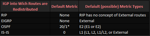
* OSPF uses cost 20 when redistributing from an IGP, and cost 1 when redistributing from BGP.


Mutual Redistribution with Multiple Routers Considerations

When multiple routers redistribute between the same two routing protocol domains, several potential problems can occur like routing loops. One type of problem occurs on the redistributing routers, because those routers will learn a route to most subnets through both routing protocols.

A router uses the AD to determine the best route when comparing the best routes from each of the two routing protocols, this typically results in some routes using suboptimal paths.

To solve this type of problem, the redistributing routers must have some awareness of
which routes came from the other routing domain. In particular, the lower-AD routing
protocol needs to decide which routes came from the higher-AD routing protocol, and
either use a different AD for those routes or filter the routes.


Preventing Suboptimal Routes by Setting the Administrative Distance

One simple solution to the problem of suboptimal routes on redistributing routers is to flag the redistributed routes with a higher AD. A route’s AD is not advertised by the routing protocol. However, a single router can be configured such that it assigns different AD values to different routes, which then impacts that one router’s choice of which routes end up in that router’s routing table.

For example, a router running redistribution between RIP/OSPF could assign an OSPF-learned route and AD of 180, an AD higher than RIP’s 120, thereby preventing the original problem. Or you can even set the default AD for OSPF external routes to 180 under OSPF process thus identifying RIP’s AD 120 the optimal route. There are several solutions.

EIGRP supports the exact same concept by default, using AD 170 for External routes
and 90 for Internal routes. You can reset EIGRP’s distance for internal and external routes by using the distance eigrp router subcommand.

The distance router subcommand can be used in a different way, influencing some of or all the routes that come from a particular router. The syntax is as follows:

distance {distance-value ip-address {wildcard-mask} [ip-standard-list] [ip-extended-list]


This command sets three key pieces of information:

1- AD to be set.

2-  IP address of the router advertising the routes.

3- ACL with which to match routes.

With RIP and EIGRP, this command identifies a neighboring router’s interface address using the ip-address wildcard-mask parameters. With OSPF, those same parameters identify the RID of the router owning (creating) the LSA for the route.  The optional ACL then identifies the subset of routes for which the AD will be set. The logic boils down to something like this:

Set this AD value for all routes learned from a router that is defined by the IP
address and wildcard mask, and for which the ACL permits the route.


Preventing Suboptimal Routes by Using Route Tags

Another method of preventing suboptimal routing on the redistributing routers is to simply filter the problematic routes.

Performing simple route filtering based on IP subnet number works, but the redistributing
routers will need to be reconfigured every time subnets change in the higher-AD routing domain. The administrative effort can be improved by adding route tagging to the process.

When you tag all routes taken from the higher-AD domain and advertised into the lower-AD domain, the distribute-list command can make a simple check for that tag.

Route tags are simply unitless integer values in the data structure of a route. These tags,
typically either 16 or 32 bits long depending on the routing protocol, allow a router to
imply something about a route that was redistributed from another routing protocol.

For example, RZ can tag its OSPF-advertised route to 10.1.2.0/24 with a tag—say, 7777. OSPF does not define what a tag of 7777 means, but the OSPF protocol includes the tag field in the LSA so that it can be used for administrative purposes. Later, RY can filter routes based on their tag, solving the suboptimal route problem.


Redistribution Between EIGRP and OSPF Lab

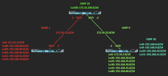
I have built a topology in the previous post about route filtering, which I will be using for this post as well. With EIGRP and OSPF, and I’ll add one more example redistributing between RIPv2 and OSPF, because the behaviour differs from protocol to protocol.

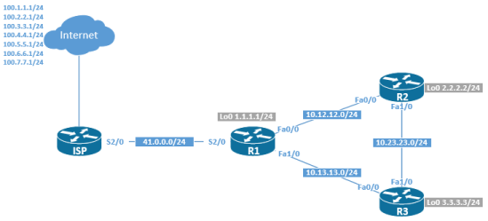
In the first lab, R1 and R2 are running EIGRP AS 1, and R2 and R3 are running OSPF. R2 is the ASBR consisting of areas 0 and 10 and R3 is an ABR running Areas 0 and 20.

Routers are running the following:

R1# sh version
Cisco IOS Software, Linux Software (I86BI_LINUX-ADVENTERPRISEK9-M), Version 15.4(2)T4, DEVELOPMENT TEST SOFTWARE
Technical Support: http://www.cisco.com/techsupport
Copyright (c) 1986-2015 by Cisco Systems, Inc.
Compiled Thu 08-Oct-15 21:21 by prod_rel_team


Topology

Filtering Routing Protocols


Scenario Objectives

  • Review EIGRP and OSPF configuration.
  • Summarize routes in EIGRP and OSPF (at the ABR/ASBR).
  • Redistribute into EIGRP.
  • Redistribute into OSPF.


Initial configuration of all loopback interfaces and serial interfaces with IP addresses and bring them up on all routers.

R1# conf t
Enter configuration commands, one per line. End with CNTL/Z.
R1(config)# int lo0
*May 30 16:00:54.416: %LINEPROTO-5-UPDOWN: Line protocol on Interface Loopback0, changed state to up
R1(config-if)# ip add 172.16.1.1 255.255.255.0
R1(config-if)# int lo48 
*May 30 16:01:17.232: %LINEPROTO-5-UPDOWN: Line protocol on Interface Loopback48, changed state to up
R1(config-if)# ip add 192.168.48.1 255.255.255.0
R1(config-if)# int lo49 
*May 30 16:01:33.901: %LINEPROTO-5-UPDOWN: Line protocol on Interface Loopback49, changed state to up
R1(config-if)# ip add 192.168.49.1 255.255.255.0
R1(config-if)# int lo50 
*May 30 16:01:43.804: %LINEPROTO-5-UPDOWN: Line protocol on Interface Loopback50, changed state to up
R1(config-if)# ip add 192.168.50.1 255.255.255.0
R1(config-if)# int lo51 
*May 30 16:01:55.899: %LINEPROTO-5-UPDOWN: Line protocol on Interface Loopback51, changed state to up
R1(config-if)# ip add 192.168.51.1 255.255.255.0
R1(config-if)# int lo70 
*May 30 16:02:07.164: %LINEPROTO-5-UPDOWN: Line protocol on Interface Loopback70, changed state to up
R1(config-if)# ip add 192.168.70.1 255.255.255.0
R1(config-if)# int s0/0
R1(config-if)# description TO-R2
R1(config-if)# ip add 172.16.12.1 255.255.255.0
R1(config-if)# clock rate threshold 64000
R1(config-if)# bandwidth 64
R1(config-if)# no shut
*May 30 16:02:58.922: %LINK-3-UPDOWN: Interface Serial0/0, changed state to up
*May 30 16:02:59.924: %LINEPROTO-5-UPDOWN: Line protocol on Interface Serial0/0, changed state to up
*May 30 16:03:21.499: %LINEPROTO-5-UPDOWN: Line protocol on Interface Serial0/0, changed state to down
R1# sh ip int bri | e admin
Interface IP-Address OK? Method Status Protocol
Serial0/0 172.16.12.1 YES manual up up 
Loopback0 172.16.1.1 YES manual up up 
Loopback48 192.168.48.1 YES manual up up 
Loopback49 192.168.49.1 YES manual up up 
Loopback50 192.168.50.1 YES manual up up 
Loopback51 192.168.51.1 YES manual up up 
Loopback70 192.168.70.1 YES manual up up 
R1#

R2# conf t
Enter configuration commands, one per line. End with CNTL/Z.
R2(config)# int lo0
*May 30 22:04:11.204: %LINEPROTO-5-UPDOWN: Line protocol on Interface Loopback0, changed state to up
R2(config-if)# ip add 172.16.2.1 255.255.255.0
R2(config)# int lo100
*May 30 19:44:47.464: %LINEPROTO-5-UPDOWN: Line protocol on Interface Loopback100, changed state to up
R2(config-if)# ip add 172.16.100.1 255.255.255.0
R2(config-if)# interface s0/0
R2(config-if)# clock rate threshold 64000
R2(config-if)# bandwidth 64
R2(config-if)# description TO->R1
R2(config-if)# ip add 172.16.12.2 255.255.255.0
R2(config-if)# no shut
*May 30 19:48:10.245: %LINK-3-UPDOWN: Interface Serial0/0, changed state to up
*May 30 19:48:11.247: %LINEPROTO-5-UPDOWN: Line protocol on Interface Serial0/0, changed state to up
R2(config-if)# int s0/1
R2(config-if)# description TO->R3
R2(config-if)# clock rate threshold 64000
R2(config-if)# bandwidth 64
R2(config-if)# ip add 172.16.23.2 255.255.255.0
R2(config-if)# no shut
*May 30 19:49:32.310: %LINK-3-UPDOWN: Interface Serial0/1, changed state to up
*May 30 19:49:33.313: %LINEPROTO-5-UPDOWN: Line protocol on Interface Serial0/1, changed state to up
R2(config-if)# end
R2# sh ip int bri | e admin
Interface IP-Address OK? Method Status Protocol
Serial0/0 172.16.12.2 YES manual up up 
Serial0/1 172.16.23.2 YES manual up up 
Loopback0 172.16.2.1 YES manual up up 
Loopback100 172.16.100.1 YES manual up up 
R2#

R3# conf t
Enter configuration commands, one per line. End with CNTL/Z.
R3(config-if)# int lo0
*May 30 21:25:40.301: %LINEPROTO-5-UPDOWN: Line protocol on Interface Loopback0, changed state to up
R3(config-if)# ip add 172.16.3.1 255.255.255.0
R3(config-if)# int lo20 
*May 30 21:25:52.609: %LINEPROTO-5-UPDOWN: Line protocol on Interface Loopback20, changed state to up
R3(config-if)# ip add 192.168.20.1 255.255.255.0
R3(config-if)# int lo25 
*May 30 21:25:59.826: %LINEPROTO-5-UPDOWN: Line protocol on Interface Loopback25, changed state to up
R3(config-if)# ip add 192.168.25.1 255.255.255.0
R3(config-if)# int lo30 
*May 30 21:26:11.917: %LINEPROTO-5-UPDOWN: Line protocol on Interface Loopback30, changed state to up
R3(config-if)# ip add 192.168.30.1 255.255.255.0
R3(config-if)# int lo35 
*May 30 21:26:19.254: %LINEPROTO-5-UPDOWN: Line protocol on Interface Loopback35, changed state to up
R3(config-if)# ip add 192.168.35.1 255.255.255.0
R3(config-if)# int lo40 
*May 30 21:26:36.641: %LINEPROTO-5-UPDOWN: Line protocol on Interface Loopback40, changed state to up
R3(config-if)# ip add 192.168.40.1 255.255.255.0
R3(config-if)# int lo8
*May 30 19:53:45.050: %LINEPROTO-5-UPDOWN: Line protocol on Interface Loopback8, changed state to up
R3(config-if)# ip add 192.168.8.1 255.255.255.0
R3(config-if)# int lo9 
*May 30 19:54:03.868: %LINEPROTO-5-UPDOWN: Line protocol on Interface Loopback9, changed state to up
R3(config-if)# ip add 192.168.9.1 255.255.255.0
R3(config-if)# int lo10 
*May 30 19:54:13.650: %LINEPROTO-5-UPDOWN: Line protocol on Interface Loopback10, changed state to up
R3(config-if)# ip add 192.168.10.1 255.255.255.0
R3(config-if)# int lo11 
*May 30 19:54:22.250: %LINEPROTO-5-UPDOWN: Line protocol on Interface Loopback11, changed state to up
R3(config-if)# ip add 192.168.11.1 255.255.255.0
R3(config-if)# exit
R3(config)# int s0/1
R3(config-if)# description TO->R2
R3(config-if)# clock rate threshold 64000
R3(config-if)# bandwidth 64
R3(config-if)# ip add 172.16.23.3 255.255.255.0
R3(config-if)# no shut
R3(config-if)# end
*May 30 20:06:54.067: %LINK-3-UPDOWN: Interface Serial0/1, changed state to up
*May 30 20:06:55.067: %LINEPROTO-5-UPDOWN: Line protocol on Interface Serial0/1, changed state to up
R3# sh ip int bri | e admin
Interface IP-Address OK? Method Status Protocol
Serial0/1 172.16.23.3 YES manual up up 
Loopback0 172.16.3.1 YES manual up up 
Loopback8 192.168.8.1 YES manual up up 
Loopback9 192.168.9.1 YES manual up up 
Loopback10 192.168.10.1 YES manual up up 
Loopback11 192.168.11.1 YES manual up up 
Loopback20 192.168.20.1 YES manual up up 
Loopback25 192.168.25.1 YES manual up up 
Loopback30 192.168.30.1 YES manual up up 
Loopback35 192.168.35.1 YES manual up up 
Loopback40 192.168.40.1 YES manual up up 
R3#


Now configure EIGRP between R1 and R2

R1> en
R1# conf t 
Enter configuration commands, one per line. End with CNTL/Z.
R1(config)# router eigrp 1
R1(config-router)# no auto-summary
R1(config-router)# network 172.16.0.0
R1(config-router)# network 192.168.48.0 0.0.255.255 
R1(config-router)#

R2> en
R2# conf t
Enter configuration commands, one per line. End with CNTL/Z.
R2(config)# router eigrp 1
R2(config-router)# no auto-summary 
R2(config-router)# network 172.16.0.0 0.0.255.255
R2(config-router)#
*Jun 14 18:13:47.355: %DUAL-5-NBRCHANGE: EIGRP-IPv4 1: Neighbor 172.16.12.1 (Serial0/0) is up: new adjacency
R2(config-router)#


Verify EIGRP configuration between R1 and R2.

R1# sh ip eigrp neighbors
EIGRP-IPv4 Neighbors for AS(1)
H Address Interface Hold Uptime SRTT RTO Q Seq
 (sec) (ms) Cnt Num
0 172.16.12.2 Se0/0 12 00:02:07 43 2340 0 3
R1# sh ip route eigrp
Codes: L - local, C - connected, S - static, R - RIP, M - mobile, B - BGP
 D - EIGRP, EX - EIGRP external, O - OSPF, IA - OSPF inter area 
 N1 - OSPF NSSA external type 1, N2 - OSPF NSSA external type 2
 E1 - OSPF external type 1, E2 - OSPF external type 2
 i - IS-IS, su - IS-IS summary, L1 - IS-IS level-1, L2 - IS-IS level-2
 ia - IS-IS inter area, * - candidate default, U - per-user static route
 o - ODR, P - periodic downloaded static route, H - NHRP, l - LISP
 a - application route
 + - replicated route, % - next hop override

Gateway of last resort is not set

 172.16.0.0/16 is variably subnetted, 7 subnets, 2 masks
D 172.16.2.0/24 [90/40640000] via 172.16.12.2, 00:00:06, Serial0/0
D 172.16.23.0/24 [90/41024000] via 172.16.12.2, 00:03:30, Serial0/0
D 172.16.100.0/24 [90/40640000] via 172.16.12.2, 00:03:30, Serial0/0
R1#

R2# sh ip eigrp neighbors
EIGRP-IPv4 Neighbors for AS(1)
H Address Interface Hold Uptime SRTT RTO Q Seq
 (sec) (ms) Cnt Num
0 172.16.12.1 Se0/0 14 00:08:20 40 2340 0 4
R2# sh ip route eigrp
Codes: L - local, C - connected, S - static, R - RIP, M - mobile, B - BGP
 D - EIGRP, EX - EIGRP external, O - OSPF, IA - OSPF inter area 
 N1 - OSPF NSSA external type 1, N2 - OSPF NSSA external type 2
 E1 - OSPF external type 1, E2 - OSPF external type 2
 i - IS-IS, su - IS-IS summary, L1 - IS-IS level-1, L2 - IS-IS level-2
 ia - IS-IS inter area, * - candidate default, U - per-user static route
 o - ODR, P - periodic downloaded static route, H - NHRP, l - LISP
 a - application route
 + - replicated route, % - next hop override

Gateway of last resort is not set

 172.16.0.0/16 is variably subnetted, 9 subnets, 2 masks
D 172.16.1.0/24 [90/40640000] via 172.16.12.1, 00:08:24, Serial0/0
D 192.168.48.0/24 [90/40640000] via 172.16.12.1, 00:08:24, Serial0/0
D 192.168.49.0/24 [90/40640000] via 172.16.12.1, 00:08:24, Serial0/0
D 192.168.50.0/24 [90/40640000] via 172.16.12.1, 00:08:24, Serial0/0
D 192.168.51.0/24 [90/40640000] via 172.16.12.1, 00:08:24, Serial0/0
D 192.168.70.0/24 [90/40640000] via 172.16.12.1, 00:08:24, Serial0/0
R2#


Now let’s test reachability between R1 and R2, use the script below to simplify the process.

R2# tclsh
R2(tcl)# foreach n {
+>(tcl)# 172.16.1.1
+>(tcl)# 192.168.48.1
+>(tcl)# 192.168.49.1
+>(tcl)# 192.168.50.1
+>(tcl)# 192.168.51.1
+>(tcl)# 192.168.70.1
+>(tcl)# 172.16.12.1
+>(tcl)# 172.16.12.2
+>(tcl)# 172.16.2.1
+>(tcl)# } {ping $n }
Type escape sequence to abort.
Sending 5, 100-byte ICMP Echos to 172.16.1.1, timeout is 2 seconds:
!!!!!
Success rate is 100 percent (5/5), round-trip min/avg/max = 31/33/34 ms
Type escape sequence to abort.
Sending 5, 100-byte ICMP Echos to 192.168.48.1, timeout is 2 seconds:
!!!!!
Success rate is 100 percent (5/5), round-trip min/avg/max = 28/30/33 ms
Type escape sequence to abort.
Sending 5, 100-byte ICMP Echos to 192.168.49.1, timeout is 2 seconds:
!!!!!
Success rate is 100 percent (5/5), round-trip min/avg/max = 30/32/34 ms
Type escape sequence to abort.
Sending 5, 100-byte ICMP Echos to 192.168.50.1, timeout is 2 seconds:
!!!!!
Success rate is 100 percent (5/5), round-trip min/avg/max = 28/32/35 ms
Type escape sequence to abort.
Sending 5, 100-byte ICMP Echos to 192.168.51.1, timeout is 2 seconds:
!!!!!
Success rate is 100 percent (5/5), round-trip min/avg/max = 30/32/34 ms
Type escape sequence to abort.
Sending 5, 100-byte ICMP Echos to 192.168.70.1, timeout is 2 seconds:
!!!!!
Success rate is 100 percent (5/5), round-trip min/avg/max = 33/33/34 ms
Type escape sequence to abort.
Sending 5, 100-byte ICMP Echos to 172.16.12.1, timeout is 2 seconds:
!!!!!
Success rate is 100 percent (5/5), round-trip min/avg/max = 31/32/34 ms
Type escape sequence to abort.
Sending 5, 100-byte ICMP Echos to 172.16.12.2, timeout is 2 seconds:
!!!!!
Success rate is 100 percent (5/5), round-trip min/avg/max = 66/66/66 ms
Type escape sequence to abort.
Sending 5, 100-byte ICMP Echos to 172.16.2.1, timeout is 2 seconds:
!!!!!
Success rate is 100 percent (5/5), round-trip min/avg/max = 4/4/5 ms
R2(tcl)#


Manually Summarize with EIGRP

To make routing updates more efficient and ultimately reduce the size of the routing table, contiguous EIGRP routes can be summarized out an interface by using the ip summary-address eigrp interface configuration command.

R1# conf t
Enter configuration commands, one per line. End with CNTL/Z.
R1(config)# interface s0/0
R1(config-if)# ip summary-address eigrp 1 192.168.48.0 255.255.254.0
R1(config-if)#
*Jun 14 19:09:33.343: %DUAL-5-NBRCHANGE: EIGRP-IPv4 1: Neighbor 172.16.12.2 (Serial0/0) is resync: summary configured
R1(config-if)# end
R1# sh ip route eigrp | b Gateway
Gateway of last resort is not set

 172.16.0.0/16 is variably subnetted, 7 subnets, 2 masks
D 172.16.2.0/24 [90/40640000] via 172.16.12.2, 00:55:45, Serial0/0
D 172.16.23.0/24 [90/41024000] via 172.16.12.2, 00:59:09, Serial0/0
D 172.16.100.0/24 [90/40640000] via 172.16.12.2, 00:59:09, Serial0/0
D 192.168.48.0/23 is a summary, 00:03:23, Null0
R1#


Verify the summarized routes in detail. Notice that the route is pointing to Null0.

R1# sh ip route 192.168.48.0 255.255.254.0
Routing entry for 192.168.48.0/23, supernet
 Known via "eigrp 1", distance 5, metric 128256, type internal
 Redistributing via eigrp 1
 Routing Descriptor Blocks:
 * directly connected, via Null0
 Route metric is 128256, traffic share count is 1
 Total delay is 5000 microseconds, minimum bandwidth is 8000000 Kbit
 Reliability 255/255, minimum MTU 1514 bytes
 Loading 1/255, Hops 0
R1#


A summary address route has an AD of 5, so it will be prefered when a device looks for a route belonging to that summary range. The fact that the route points to interface Null0 is a loop prevention mechanism. What it does is silently drops traffic requesting routes within the summary address range but are not advertised by the router or not present on the routing table. In other words, a route might not exist in the routing table but still be within the summary address range. When this occurs, traffic is silently dropped as a loop prevention mechanism.


Now let’s verify the routing table on R2. Note that the summary address is in the table.

R2> sh ip route eigrp | b Gateway
Gateway of last resort is not set

172.16.0.0/16 is variably subnetted, 9 subnets, 2 masks
D 172.16.1.0/24 [90/40640000] via 172.16.12.1, 03:04:49, Serial0/0
D 192.168.48.0/23 [90/40640000] via 172.16.12.1, 00:00:26, Serial0/0
D 192.168.50.0/24 [90/40640000] via 172.16.12.1, 03:04:49, Serial0/0
D 192.168.51.0/24 [90/40640000] via 172.16.12.1, 03:04:49, Serial0/0
D 192.168.70.0/24 [90/40640000] via 172.16.12.1, 03:04:49, Serial0/0
R2>


Now, because we configured EIGRP with one statement covering the 172.16.0.0/16 range, all interfaces configured with any address in that same range are participating in EIGRP. In the case of R1 it does not have negative affect as R1 only connects to R2 running EIGRP. Let’s take a look.

R2# sh ip eigrp interfaces 
EIGRP-IPv4 Interfaces for AS(1)
 Xmit Queue PeerQ Mean Pacing Time Multicast Pending
Interface Peers Un/Reliable Un/Reliable SRTT Un/Reliable Flow Timer Routes
Se0/0 1 0/0 0/0 44 10/390 546 0
Se0/1 0 0/0 0/0 0 10/10 0 0
Lo0 0 0/0 0/0 0 0/0 0 0
Lo100 0 0/0 0/0 0 0/0 0 0
R2#


The serial interface s0/1 connected to R3 is sending and receiving EIGRP packets but it’s supposed to process only OSPF packets and exchange neighbor information with R3. Let’s prevent R2 from processing EIGRP packets on the serial link connected to R3.

R2# conf t
Enter configuration commands, one per line. End with CNTL/Z.
R2(config)# router eigrp 1
R2(config-router)# passive-interface s0/1
R2(config-router)# end
R2#
R2# sh ip protocols 
*** IP Routing is NSF aware ***
Routing Protocol is "eigrp 1"
 <output omitted>
  Automatic Summarization: disabled
 Maximum path: 4
 Routing for Networks:
 172.16.0.0
 Passive Interface(s):
 Serial0/1
 Routing Information Sources:
 Gateway Distance Last Update
 172.16.12.1 90 00:01:24
 Distance: internal 90 external 170


That’s more like it! We now have only s0/0 interface connected to R1 running and processing EIGRP packets. Alrighty then!


Configure OSPF on and between R2 and R3

Now let’s configure R3 and R2 to run OSPF, beginning on R3.

R3# conf t
Enter configuration commands, one per line. End with CNTL/Z.
R3(config)# router ospf 1
R3(config-router)# network 172.16.3.1 0.0.0.0 area 0
R3(config-router)# network 172.16.23.3 0.0.0.0 area 0
R3(config-router)# network 192.168.8.0 0.0.3.255 area 20
R3(config-router)# network 192.168.20.1 0.0.0.0 area 0
R3(config-router)# network 192.168.25.1 0.0.0.0 area 0
R3(config-router)# network 192.168.30.1 0.0.0.0 area 0
R3(config-router)# network 192.168.35.1 0.0.0.0 area 0
R3(config-router)# network 192.168.40.1 0.0.0.0 area 0
R3(config-router)#

R2# conf t
Enter configuration commands, one per line. End with CNTL/Z.
R2(config)# router ospf 1
R2(config-router)# network 172.16.23.0 0.0.0.255 area 0
R2(config-router)# network 172.16.100.0 0.0.0.255 area 10
R2(config-router)#
*Jun 15 04:19:01.385: %OSPF-5-ADJCHG: Process 1, Nbr 192.168.40.1 on Serial0/1 from LOADING to FULL, Loading Done
R2(config-router)#


Verify that your adjacencies come up and make sure that you have routes from OSPF populating the R2 routing table.

R2# sh ip ospf neighbor

Neighbor ID Pri State Dead Time Address Interface
192.168.40.1 0 FULL/ - 00:00:35 172.16.23.3 Serial0/1
R2#

R3# sh ip ospf neighbor

Neighbor ID Pri State Dead Time Address Interface
172.16.100.1 0 FULL/ - 00:00:31 172.16.23.2 Serial0/1
R3#

R2# show ip route ospf | b Gateway
Gateway of last resort is not set

 172.16.0.0/16 is variably subnetted, 10 subnets, 2 masks
O 172.16.3.0/24 [110/1563] via 172.16.23.3, 00:08:26, Serial0/1
O IA 192.168.8.0/24 [110/1563] via 172.16.23.3, 00:08:26, Serial0/1
O IA 192.168.9.0/24 [110/1563] via 172.16.23.3, 00:08:26, Serial0/1
O IA 192.168.10.0/24 [110/1563] via 172.16.23.3, 00:08:26, Serial0/1
O IA 192.168.11.0/24 [110/1563] via 172.16.23.3, 00:08:26, Serial0/1
O 192.168.20.0/24 [110/1563] via 172.16.23.3, 00:08:26, Serial0/1
O 192.168.25.0/24 [110/1563] via 172.16.23.3, 00:08:26, Serial0/1
O 192.168.30.0/24 [110/1563] via 172.16.23.3, 00:08:26, Serial0/1
O 192.168.35.0/24 [110/1563] via 172.16.23.3, 00:08:26, Serial0/1
O 192.168.40.0/24 [110/1563] via 172.16.23.3, 00:08:26, Serial0/1
R2#


We’re good to go!


Summarize OSPF Areas at the ABR

Now let’s review the R2 routing table, and notice the Inter-area routes being advertised from R3 loopbacks in area 20. We can do a better job advertizing all these routes.

R2# show ip route ospf | b Gateway
Gateway of last resort is not set

172.16.0.0/16 is variably subnetted, 10 subnets, 2 masks
O 172.16.3.0/24 [110/1563] via 172.16.23.3, 00:08:26, Serial0/1
O IA 192.168.8.0/24 [110/1563] via 172.16.23.3, 00:08:26, Serial0/1
O IA 192.168.9.0/24 [110/1563] via 172.16.23.3, 00:08:26, Serial0/1
O IA 192.168.10.0/24 [110/1563] via 172.16.23.3, 00:08:26, Serial0/1
O IA 192.168.11.0/24 [110/1563] via 172.16.23.3, 00:08:26, Serial0/1
O 192.168.20.0/24 [110/1563] via 172.16.23.3, 00:08:26, Serial0/1
O 192.168.25.0/24 [110/1563] via 172.16.23.3, 00:08:26, Serial0/1
O 192.168.30.0/24 [110/1563] via 172.16.23.3, 00:08:26, Serial0/1
O 192.168.35.0/24 [110/1563] via 172.16.23.3, 00:08:26, Serial0/1
O 192.168.40.0/24 [110/1563] via 172.16.23.3, 00:08:26, Serial0/1
R2#


Let’s summarize the routes from area 20 into a single Inter-area route on R3. This way, we can have a nice and tidy routing table which not only can be better analyzed but also helps on resources.

R3# conf t
Enter configuration commands, one per line. End with CNTL/Z.
R3(config)# router ospf 1
R3(config-router)# area 20 range 192.168.8.0 255.255.252.0
R3(config-router)#


Verify on R2 that you are now receiving the summarized route from R3.

R2# show ip route ospf | b Gateway
Gateway of last resort is not set

172.16.0.0/16 is variably subnetted, 10 subnets, 2 masks
O 172.16.3.0/24 [110/1563] via 172.16.23.3, 00:17:59, Serial0/1
O IA 192.168.8.0/22 [110/1563] via 172.16.23.3, 00:00:26, Serial0/1
O 192.168.20.0/24 [110/1563] via 172.16.23.3, 00:17:59, Serial0/1
O 192.168.25.0/24 [110/1563] via 172.16.23.3, 00:17:59, Serial0/1
O 192.168.30.0/24 [110/1563] via 172.16.23.3, 00:17:59, Serial0/1
O 192.168.35.0/24 [110/1563] via 172.16.23.3, 00:17:59, Serial0/1
O 192.168.40.0/24 [110/1563] via 172.16.23.3, 00:17:59, Serial0/1
R2#


Configure mutual redistribution between OSPF and EIGRP

Now let’s configure redistribution between both routing protocols. R2 is the ASBR for the OSPF domain and EIGRP AS, so it will be the key point for redistribution.

The subnets command is necessary because, by default, OSPF only redistributes classful networks and supernets. A default seed metric is not required for OSPF. Under the EIGRP process, we need to tell EIGRP to redistribute OSPF process 1 with specific metrics: bandwidth of 10000, delay of 100, reliability of 255/255, load of 1/255, and a MTU of 1500. Like RIP, EIGRP requires a seed metric. You can also set a default seed metric with the default-metric command.

R2# conf t
Enter configuration commands, one per line. End with CNTL/Z.
R2(config)# router ospf 1
R2(config-router)# redistribute eigrp 1 subnets 
R2(config-router)# exit
R2(config)# router eigrp 1
R2(config-router)# redistribute ospf 1 metric 10000 100 255 1 1500
R2(config-router)#


We could also define a default seed metric and just redistribute the OSPF process. Both of the commands work the same way.

R2(config-router)# default-metric 10000 100 255 1 1500
R2(config-router)# redistribute ospf 1


Now let’s verify the change on the redistributing router R2.

R2# sh ip protocols 
*** IP Routing is NSF aware ***

Routing Protocol is "application"
 Sending updates every 0 seconds
 Invalid after 0 seconds, hold down 0, flushed after 0
 Outgoing update filter list for all interfaces is not set
 Incoming update filter list for all interfaces is not set
 Maximum path: 32
 Routing for Networks:
 Routing Information Sources:
 Gateway Distance Last Update
 Distance: (default is 4)

Routing Protocol is "eigrp 1"
 Outgoing update filter list for all interfaces is not set
 Incoming update filter list for all interfaces is not set
 Default networks flagged in outgoing updates
 Default networks accepted from incoming updates
 Redistributing: ospf 1
 EIGRP-IPv4 Protocol for AS(1)
 Metric weight K1=1, K2=0, K3=1, K4=0, K5=0
 NSF-aware route hold timer is 240
 Router-ID: 172.16.100.1
 Topology : 0 (base) 
 Active Timer: 3 min
 Distance: internal 90 external 170
 Maximum path: 4
 Maximum hopcount 100
 Maximum metric variance 1

Automatic Summarization: disabled
 Maximum path: 4
 Routing for Networks:
 172.16.0.0
 Passive Interface(s):
 Serial0/1
 Routing Information Sources:
 Gateway Distance Last Update
 172.16.12.1 90 00:56:10
 Distance: internal 90 external 170

Routing Protocol is "ospf 1"
 Outgoing update filter list for all interfaces is not set
 Incoming update filter list for all interfaces is not set
 Router ID 172.16.100.1
 It is an area border and autonomous system boundary router
 Redistributing External Routes from,
 eigrp 1, includes subnets in redistribution
 Number of areas in this router is 2. 2 normal 0 stub 0 nssa
 Maximum path: 4
 Routing for Networks:
 172.16.23.0 0.0.0.255 area 0
 172.16.100.0 0.0.0.255 area 10
 Routing Information Sources:
 Gateway Distance Last Update
 192.168.40.1 110 00:38:28
 Distance: (default is 110)

R2#


Now let’s verify the routing tables on R1 and R3 so that we can see the redistributed routes. Redistributed OSPF routes display on R1 as D EX, (External EIGRP routes – AD 170). Redistributed EIGRP routes are tagged in R3’s routing table as O E2, (OSPF External Type 2, which do not increment their metric as they traverse the path). Type 2 is the default OSPF External Type.

R1> sh ip route eigrp | b Gateway
Gateway of last resort is not set

172.16.0.0/16 is variably subnetted, 8 subnets, 2 masks
D 172.16.2.0/24 [90/40640000] via 172.16.12.2, 01:13:39, Serial0/0
D EX 172.16.3.0/24 [170/40537600] via 172.16.12.2, 00:09:59, Serial0/0
D 172.16.23.0/24 [90/41024000] via 172.16.12.2, 01:13:39, Serial0/0
D 172.16.100.0/24 [90/40640000] via 172.16.12.2, 01:13:39, Serial0/0
D EX 192.168.8.0/22 [170/40537600] via 172.16.12.2, 00:09:59, Serial0/0
D EX 192.168.20.0/24 [170/40537600] via 172.16.12.2, 00:09:59, Serial0/0
D EX 192.168.25.0/24 [170/40537600] via 172.16.12.2, 00:09:59, Serial0/0
D EX 192.168.30.0/24 [170/40537600] via 172.16.12.2, 00:09:59, Serial0/0
D EX 192.168.35.0/24 [170/40537600] via 172.16.12.2, 00:09:59, Serial0/0
D EX 192.168.40.0/24 [170/40537600] via 172.16.12.2, 00:09:59, Serial0/0
D 192.168.48.0/23 is a summary, 01:47:52, Null0
R1>

R3> sh ip route ospf | b Gateway
Gateway of last resort is not set

 172.16.0.0/16 is variably subnetted, 8 subnets, 2 masks
O E2 172.16.1.0/24 [110/20] via 172.16.23.2, 00:13:39, Serial0/1
O E2 172.16.2.0/24 [110/20] via 172.16.23.2, 00:13:39, Serial0/1
O E2 172.16.12.0/24 [110/20] via 172.16.23.2, 00:13:39, Serial0/1
O IA 172.16.100.0/24 [110/1563] via 172.16.23.2, 00:45:51, Serial0/1
O 192.168.8.0/22 is a summary, 00:45:51, Null0
O E2 192.168.48.0/23 [110/20] via 172.16.23.2, 00:13:39, Serial0/1
O E2 192.168.50.0/24 [110/20] via 172.16.23.2, 00:13:39, Serial0/1
O E2 192.168.51.0/24 [110/20] via 172.16.23.2, 00:13:39, Serial0/1
O E2 192.168.70.0/24 [110/20] via 172.16.23.2, 00:13:39, Serial0/1
R3>


Now, let’s verify full reachability between all segments on both R1 and R3. I’m not putting the output of the echo replies, kinda too long but it’s working, nothing is missing on my side.

R1# tclsh
R1(tcl)#foreach n {
+>(tcl)#172.16.1.1
+>(tcl)#192.168.48.1
+>(tcl)#192.168.49.1
+>(tcl)#192.168.50.1
+>(tcl)#192.168.51.1
+>(tcl)#192.168.70.1
+>(tcl)#172.16.12.1
+>(tcl)#172.16.12.2
+>(tcl)#172.16.2.1
+>(tcl)#172.16.100.1
+>(tcl)#172.16.23.2
+>(tcl)#172.16.23.3
+>(tcl)#172.16.3.1
+>(tcl)#192.168.8.1
+>(tcl)#192.168.9.1
+>(tcl)#192.168.10.1
+>(tcl)#192.168.11.1
+>(tcl)#192.168.20.1
+>(tcl)#192.168.25.1
+>(tcl)#192.168.30.1
+>(tcl)#192.168.35.1
+>(tcl)#192.168.40.1
+>(tcl)# } {ping $n }


Summarize external routes into OSPF at the ASBR

Now let’s summarize those EIGRP routes that R1 is advertising as a summary address range onR2, the ASBR for OSPF domain, but first let’s look at R3’s routing table.

R3> sh ip route ospf | b Gateway
Gateway of last resort is not set

172.16.0.0/16 is variably subnetted, 8 subnets, 2 masks
O E2 172.16.1.0/24 [110/20] via 172.16.23.2, 00:32:36, Serial0/1
O E2 172.16.2.0/24 [110/20] via 172.16.23.2, 00:32:36, Serial0/1
O E2 172.16.12.0/24 [110/20] via 172.16.23.2, 00:32:36, Serial0/1
O IA 172.16.100.0/24 [110/1563] via 172.16.23.2, 01:04:48, Serial0/1
O 192.168.8.0/22 is a summary, 01:04:48, Null0
O E2 192.168.48.0/23 [110/20] via 172.16.23.2, 00:32:36, Serial0/1
O E2 192.168.50.0/24 [110/20] via 172.16.23.2, 00:32:36, Serial0/1
O E2 192.168.51.0/24 [110/20] via 172.16.23.2, 00:32:36, Serial0/1
O E2 192.168.70.0/24 [110/20] via 172.16.23.2, 00:32:36, Serial0/1
R3>


We are receiving the 192.168.48.0/23 summary configured on R1 and advertised by EIGRP, which is being redistributed from R2, but, we are still receiving the individual routes that belong to that summary address. Let’s fix it by configuring a supernet on R2 and prevent the individual routes from being advertised.

R2# conf t
Enter configuration commands, one per line. End with CNTL/Z.
R2(config)# router ospf 1
R2(config-router)# summary-address 192.168.48.0 255.255.252.0
R2(config-router)#

R3> sh ip route ospf | b Gateway
Gateway of last resort is not set

 172.16.0.0/16 is variably subnetted, 8 subnets, 2 masks
O E2 172.16.1.0/24 [110/20] via 172.16.23.2, 00:36:57, Serial0/1
O E2 172.16.2.0/24 [110/20] via 172.16.23.2, 00:36:57, Serial0/1
O E2 172.16.12.0/24 [110/20] via 172.16.23.2, 00:36:57, Serial0/1
O IA 172.16.100.0/24 [110/1563] via 172.16.23.2, 01:09:09, Serial0/1
O 192.168.8.0/22 is a summary, 01:09:09, Null0
O E2 192.168.48.0/22 [110/20] via 172.16.23.2, 00:00:01, Serial0/1
O E2 192.168.70.0/24 [110/20] via 172.16.23.2, 00:36:57, Serial0/1
R3>


That looks a lot better.


Redistribution between RIPv2 and OSPF

Now let’s clear the EIGRP configuration and replace it with RIPv2. Perform the redistribution but this time between OSPF and RIPv2.


Objectives

• Review configuration and verification of RIP and OSPF.
• Configure passive interfaces in both RIP and OSPF.
• Filter routing updates using distribute lists.
• Redistribute static routes into RIP.
• Redistribute RIP routes into OSPF.
• Redistribute OSPF routes into RIP.
• Originate a default route into OSPF.
• Set a default seed metric.
• Modify OSPF external network types.
• Configure summary addresses.


Let’s begin on R1 and then R2.

R1# conf t
R1(config)# no router eigrp 1 
R1(config)# router rip 
R1(config-router)# version 2
R1(config-router)# no auto-summary 
R1(config-router)# network 172.16.0.0
R1(config-router)# network 192.168.48.0
R1(config-router)# network 192.168.49.0
R1(config-router)# network 192.168.50.0
R1(config-router)# network 192.168.51.0
R1(config-router)# network 192.168.70.0

R2# conf t
Enter configuration commands, one per line. End with CNTL/Z.
R2(config)# no router eigrp 1
R2(config)# router ospf 1
R2(config-router)# no summary-address 192.168.48.0 255.255.252.0
R2(config-router)# router rip 
R2(config-router)# version 2
R2(config-router)# no auto-summary
R2(config-router)# network 172.16.0.0
R2(config-router)#


Let’s verify that the RIP routes were learned from both routers. Also, let’s verify which routes are coming in from RIP advertisements.

R2# sh ip route rip | b Gateway
Gateway of last resort is not set

172.16.0.0/16 is variably subnetted, 10 subnets, 2 masks
R 172.16.1.0/24 [120/1] via 172.16.12.1, 00:00:19, Serial0/0
R 192.168.48.0/24 [120/1] via 172.16.12.1, 00:00:19, Serial0/0
R 192.168.49.0/24 [120/1] via 172.16.12.1, 00:00:19, Serial0/0
R 192.168.50.0/24 [120/1] via 172.16.12.1, 00:00:19, Serial0/0
R 192.168.51.0/24 [120/1] via 172.16.12.1, 00:00:19, Serial0/0
R 192.168.70.0/24 [120/1] via 172.16.12.1, 00:00:19, Serial0/0
R2# sh ip rip database
172.16.0.0/16 auto-summary
172.16.1.0/24
 [1] via 172.16.12.1, 00:00:04, Serial0/0
172.16.2.0/24 directly connected, Loopback0
172.16.12.0/24 directly connected, Serial0/0
172.16.23.0/24 directly connected, Serial0/1
172.16.100.0/24 directly connected, Loopback100
192.168.48.0/24 auto-summary
192.168.48.0/24
 [1] via 172.16.12.1, 00:00:04, Serial0/0
192.168.49.0/24 auto-summary
192.168.49.0/24
 [1] via 172.16.12.1, 00:00:04, Serial0/0
192.168.50.0/24 auto-summary
192.168.50.0/24
 [1] via 172.16.12.1, 00:00:04, Serial0/0
192.168.51.0/24 auto-summary
192.168.51.0/24
 [1] via 172.16.12.1, 00:00:04, Serial0/0
192.168.70.0/24 auto-summary
192.168.70.0/24
 [1] via 172.16.12.1, 00:00:04, Serial0/0
R2#

R1# sh ip route rip | b Gateway
Gateway of last resort is not set

 172.16.0.0/16 is variably subnetted, 7 subnets, 2 masks
R 172.16.2.0/24 [120/1] via 172.16.12.2, 00:00:24, Serial0/0
R 172.16.23.0/24 [120/1] via 172.16.12.2, 00:00:24, Serial0/0
R 172.16.100.0/24 [120/1] via 172.16.12.2, 00:00:24, Serial0/0
R1# sh ip rip database
172.16.0.0/16 auto-summary
172.16.1.0/24 directly connected, Loopback0
172.16.2.0/24
 [1] via 172.16.12.2, 00:00:17, Serial0/0
172.16.12.0/24 directly connected, Serial0/0
172.16.23.0/24
 [1] via 172.16.12.2, 00:00:17, Serial0/0
172.16.100.0/24
 [1] via 172.16.12.2, 00:00:17, Serial0/0
192.168.48.0/24 auto-summary
192.168.48.0/24 directly connected, Loopback48
192.168.49.0/24 auto-summary
192.168.49.0/24 directly connected, Loopback49
192.168.50.0/24 auto-summary
192.168.50.0/24 directly connected, Loopback50
192.168.51.0/24 auto-summary
192.168.51.0/24 directly connected, Loopback51
192.168.70.0/24 auto-summary
192.168.70.0/24 directly connected, Loopback70
R1#


Just by looking at it its easy to see that this is not properly configured, to begin with, the segments 172.16.23.0/24 and 172.16.100.0/24 are being advertised by OSPF. Let’s use the passive interfaces on R2 and observe RIP’s behaviour, also check R1’s routing table.

R2# conf t
Enter configuration commands, one per line. End with CNTL/Z.
R2(config)# router rip
R2(config-router)# passive-interface default
R2(config-router)# no passive-interface Serial0/0
R2(config-router)#

R1# sh ip route rip | b Gateway
Gateway of last resort is not set

 172.16.0.0/16 is variably subnetted, 7 subnets, 2 masks
R 172.16.2.0/24 [120/1] via 172.16.12.2, 00:00:11, Serial0/0
R 172.16.23.0/24 [120/1] via 172.16.12.2, 00:00:11, Serial0/0
R 172.16.100.0/24 [120/1] via 172.16.12.2, 00:00:11, Serial0/0
R1#


R2’s segments being advertised by OSPF are still being advertised by RIP even after we issued the passive interfaces command and specifically configure only s0/0 interface as being part of RIP.  Making an interface in RIP passive only disables updates from being sent through RIP. It does not affect routes being received through it as RIP advertises at classful boundaries.

Also note that when running RIPv2 (not sure why you would want to do that but…), implement passive interfaces as a common practice to save CPU processor cycles and bandwidth on interfaces that do not have to multicast to RIPv2 neighbors. (You can do this on Loopback interfaces also as no neighbor is expected to send/receive updates).


Summarize a supernet with RIP

Let’s configure a supernet summarizing those segments from R1. Note that,  In preparing for redistribution, you want to redistribute the minimum number of destination prefixes possible into each of the routing protocols.

Under normal circumstances, you could simply summarize the four consecutive class-C networks with the ip summary address rip command on the R1 serial 0/0 interface.

However, as mentioned above, RIP implementation in Cisco IOS does not allow summarizing to a mask length that is less than the classful network prefix (in this case, 24 bits). This limitation does not affect other routing protocols. For the purpose of the example here, I’m configuring it below and received the following error message:

R1# conf t
Enter configuration commands, one per line. End with CNTL/Z.
R1(config)# interface s0/0
R1(config-if)# ip summary-address rip 192.168.48.0 255.255.252.0
 Summary mask must be greater or equal to major net
R1(config-if)#


The solution here with RIP, is to turn it around. Remember from the previous EIGRP lab that summary routes display in the summarizing device’s routing table as having the next hop being the Null0 interface.

We can create an entry manually by using a static route pointing to Null0 and redistribute it into RIP, thereby emulating the approach of EIGRP to a certain extent.

R1(config)# ip route 192.168.48.0 255.255.252.0 null0
R1(config)# router rip
R1(config-router)# redistribute static
R1(config-router)# end
R1#
*Jun 15 09:44:18.465: %SYS-5-CONFIG_I: Configured from console by console
R1#
R1# sh ip route | e L|C
 D - EIGRP, EX - EIGRP external, O - OSPF, IA - OSPF inter area 
 N1 - OSPF NSSA external type 1, N2 - OSPF NSSA external type 2
 E1 - OSPF external type 1, E2 - OSPF external type 2
 ia - IS-IS inter area, * - candidate default, U - per-user static route
 a - application route
 + - replicated route, % - next hop override

Gateway of last resort is not set

172.16.0.0/16 is variably subnetted, 7 subnets, 2 masks
R 172.16.2.0/24 [120/1] via 172.16.12.2, 00:00:03, Serial0/0
R 172.16.23.0/24 [120/1] via 172.16.12.2, 00:00:03, Serial0/0
R 172.16.100.0/24 [120/1] via 172.16.12.2, 00:00:03, Serial0/0
S 192.168.48.0/22 is directly connected, Null0
 192.168.48.0/24 is variably subnetted, 2 subnets, 2 masks
 192.168.49.0/24 is variably subnetted, 2 subnets, 2 masks
 192.168.50.0/24 is variably subnetted, 2 subnets, 2 masks
 192.168.51.0/24 is variably subnetted, 2 subnets, 2 masks
 192.168.70.0/24 is variably subnetted, 2 subnets, 2 masks

R1#


Note:  For RIPv2, it resembles many effects of summarization as performed in other routing protocols like EIGRP or OSPF. Bare in mind, this is not a limitation of RIPv2, but rather a Cisco IOS implementation issue.


On R2, verify that the RIP supernet has been added to the routing table.

R2> sh ip route rip | b Gateway
Gateway of last resort is not set

172.16.0.0/16 is variably subnetted, 10 subnets, 2 masks
R 172.16.1.0/24 [120/1] via 172.16.12.1, 00:00:19, Serial0/0
R 192.168.48.0/22 [120/1] via 172.16.12.1, 00:00:19, Serial0/0
R 192.168.48.0/24 [120/1] via 172.16.12.1, 00:00:19, Serial0/0
R 192.168.49.0/24 [120/1] via 172.16.12.1, 00:00:19, Serial0/0
R 192.168.50.0/24 [120/1] via 172.16.12.1, 00:00:19, Serial0/0
R 192.168.51.0/24 [120/1] via 172.16.12.1, 00:00:19, Serial0/0
R 192.168.70.0/24 [120/1] via 172.16.12.1, 00:00:19, Serial0/0
R2>


And sure enough we are advertising the supernet from R1 but R2 is still receiving each individual route belonging to that summarized range. Just for an example on how to configure on RIP, I’m going to perform some route filtering.


Route Filtering with RIPv2

If you need to advertise certain networks out a particular interface, or you might want to filter updates as they come in, this is possible with distance-vector routing protocols, such as RIP or EIGRP. However, link-state protocols are less flexible, because every router in an area is required to have a synchronized database as a condition for full adjacency.

Distribute lists can be used with either access lists or prefix lists to filter routes by network address. With prefix lists, they can also be configured to filter routes by subnet masks.

In this scenario, you want to filter updates from R1 to R2, allowing only the networks of Loopback 0 and Loopback 70 and the summary route to be advertised.

You want to suppress the more specific prefixes so that routing tables are kept small, and CPU processor cycles on the routers are not wasted.

The 22-bit summary and the 24-bit major network address both have the same address, so access lists will not accomplish the filtering correctly. Therefore, it is necessary to use prefix lists.

In my previous post on Route Filtering, I covered ACLs, Prefix Lists, Route Maps and Distribute Lists in depth. Remember,  the ge keyword represents the “greater than or equal to” operator. The le keyword represents the “less than or equal to” operator. If both the ge and le keywords are omitted, the prefix list is processed using an exact match.

On R1, use a prefix list as a distribution filter to prevent the more specific routes from loopbacks 48 through 51 from being advertised. Allow all other destination networks, including the summary route.

R1> en
R1# conf t
Enter configuration commands, one per line. End with CNTL/Z.
R1(config)# ip prefix-list RIP-OUT permit 192.168.48.0/22
R1(config)# ip prefix-list RIP-OUT deny 192.168.48.0/22 le 24
R1(config)# ip prefix-list RIP-OUT permit 0.0.0.0/0 le 32
R1(config)#


Let’s analyze what we just configured.  Line 1 of the prefix list permits the summary route and nothing else, because no other route can match that network address with a mask of exactly 22 bits. Line 2 denies all prefixes with a network address in the 192.168.48.0/22 block of addresses that have subnet masks from 22 bits to 24 bits. This removes exactly four network addresses matching the 22, 23, and 24 bits in length of the subnet mask.

Line 2 would deny the 192.168.48.0/22 summary route we created if Line 1 did not explicitly permit the summary route. Line 3 allows all IPv4 prefixes that are not explicitly denied in previous statements of the prefix list.

From the RIP configuration process on R1, apply this prefix list with a distribute-list. Verify R2 routing table afterwards.

R1(config)# router rip
R1(config-router)# distribute-list prefix RIP-OUT out s0/0
R1(config-router)# do sh ip prefix-list
ip prefix-list RIP-OUT: 3 entries
 seq 5 permit 192.168.48.0/22
 seq 10 deny 192.168.48.0/22 le 24
 seq 15 permit 0.0.0.0/0 le 32
R1(config-router)# 

R2# clear ip route * 
R2# sh ip route rip | b Gateway
Gateway of last resort is not set

 172.16.0.0/16 is variably subnetted, 10 subnets, 2 masks
R 172.16.1.0/24 [120/1] via 172.16.12.1, 00:00:06, Serial0/0
R 192.168.48.0/22 [120/1] via 172.16.12.1, 00:00:06, Serial0/0
R 192.168.70.0/24 [120/1] via 172.16.12.1, 00:00:06, Serial0/0
R2# sh ip rip database
172.16.0.0/16 auto-summary
172.16.1.0/24
 [1] via 172.16.12.1, 00:00:05, Serial0/0
172.16.2.0/24 directly connected, Loopback0
172.16.12.0/24 directly connected, Serial0/0
172.16.23.0/24 directly connected, Serial0/1
172.16.100.0/24 directly connected, Loopback100
192.168.48.0/22
 [1] via 172.16.12.1, 00:00:05, Serial0/0
192.168.70.0/24 auto-summary
192.168.70.0/24
 [1] via 172.16.12.1, 00:00:05, Serial0/0
R2#


Note: This could have been achieved by using the out rip syntax instead of the out s0/0. This would allow only the selected prefixes to leave RIP updates. Both accomplish the same goal.

Just for fun, let’s configure that 172.16.23.0/24 segment from being advertised on RIP. Afterall, it belongs to the OSPF process between R2 and R3. I’m also using a prefix list to achieve this goal. First let’s analyze R1’s routing table.

R1# sh ip route rip | b Gateway
Gateway of last resort is not set

172.16.0.0/16 is variably subnetted, 7 subnets, 2 masks
R 172.16.2.0/24 [120/1] via 172.16.12.2, 00:00:37, Serial0/0
R 172.16.23.0/24 [120/1] via 172.16.12.2, 00:00:37, Serial0/0
R 172.16.100.0/24 [120/1] via 172.16.12.2, 00:00:37, Serial0/0
R1#


Alrighty then! Let’s filter that route and verify the result on R1’s routing table.

R2# conf t
Enter configuration commands, one per line. End with CNTL/Z.
R2(config)# ip prefix-list FILTER_172.23_->rip deny 172.16.23.0/24
R2(config)# ip prefix-list FILTER_172.23_->rip permit 0.0.0.0/0 le 32
R2(config)# router rip
R2(config-router)# distribute-list prefix FILTER_172.23_->rip out s0/0 
R2(config-router)# end
R2#

R1# sh ip route rip | b Gateway
Gateway of last resort is not set

 172.16.0.0/16 is variably subnetted, 6 subnets, 2 masks
R 172.16.2.0/24 [120/1] via 172.16.12.2, 00:00:03, Serial0/0
R 172.16.100.0/24 [120/1] via 172.16.12.2, 00:00:03, Serial0/0
R1# sh ip route 172.16.23.0 255.255.255.0
% Subnet not in table
R1#


And there it is, the segment was filtered!


Now, let’s make a slight configuration change with a single-area OSPF between R2 and R3. On R2, include just the s0/1 link connecting to R3 (the segment we just filtered out of RIP advertisements. On R3, include the serial link and all loopback interfaces.

R2(config)# router ospf 1
R2(config-router)# passive-interface default 
*Jun 15 11:15:51.363: %OSPF-5-ADJCHG: Process 1, Nbr 192.168.40.1 on Serial0/1 from FULL to DOWN, Neighbor Down: Interface down or detached
R2(config-router)# no passive-interface s0/1
*Jun 15 11:15:56.130: %OSPF-5-ADJCHG: Process 1, Nbr 192.168.40.1 on Serial0/1 from LOADING to FULL, Loading Done
R2(config-router)# do sh run | s ospf 1
router ospf 1
 passive-interface default
 no passive-interface Serial0/1
 network 172.16.23.0 0.0.0.255 area 0
 network 172.16.100.0 0.0.0.255 area 10
R2(config-router)# no network 172.16.100.0 0.0.0.255 area 10
R2(config-router)# do sh run | s router
router ospf 1
 passive-interface default
 no passive-interface Serial0/1
 network 172.16.23.0 0.0.0.255 area 0
R2(config-router)# end
R2# sh ip ospf neighbor 

Neighbor ID Pri State Dead Time Address Interface
192.168.40.1 0 FULL/ - 00:00:30 172.16.23.3 Serial0/1
R2#


R3# conf t
Enter configuration commands, one per line. End with CNTL/Z.
R3(config)# router ospf 1
R3(config-router)# network 172.16.0.0 0.0.255.255 area 0
R3(config-router)# network 192.168.0.0 0.0.255.255 area 0
R3(config-router)# end
R3# sh ip ospf neighbor 

Neighbor ID Pri State Dead Time Address Interface
172.16.100.1 0 FULL/ - 00:00:31 172.16.23.2 Serial0/1
R3#


Verification on router R2’s routing table.

R2# sh ip route ospf | b Gateway
Gateway of last resort is not set

172.16.0.0/16 is variably subnetted, 10 subnets, 2 masks
O 172.16.3.0/24 [110/1563] via 172.16.23.3, 00:25:17, Serial0/1
O 192.168.8.0/24 [110/1563] via 172.16.23.3, 00:25:00, Serial0/1
O 192.168.9.0/24 [110/1563] via 172.16.23.3, 00:25:00, Serial0/1
O 192.168.10.0/24 [110/1563] via 172.16.23.3, 00:25:00, Serial0/1
O 192.168.11.0/24 [110/1563] via 172.16.23.3, 00:25:00, Serial0/1
O 192.168.20.0/24 [110/1563] via 172.16.23.3, 00:25:00, Serial0/1
O 192.168.25.0/24 [110/1563] via 172.16.23.3, 00:25:00, Serial0/1
O 192.168.30.0/24 [110/1563] via 172.16.23.3, 00:25:00, Serial0/1
O 192.168.35.0/24 [110/1563] via 172.16.23.3, 00:25:00, Serial0/1
O 192.168.40.0/24 [110/1563] via 172.16.23.3, 00:25:00, Serial0/1
R2#


Allow One-Way Redistribution

On R2, let’s configure RIP to redistribute OSPF routes into RIP. Note that the metric is the default metric with which you want to originate the routes into RIP. If you do not specify a default metric in RIP, it gives routes an infinite metric and they are not advertised. Let’s give it a metric of 5.

R2# conf t
R2(config)# router rip
R2(config-router)# redistribute ospf 1 metric 5
R2(config-router)# end
*Jun 16 09:25:18.305: %SYS-5-CONFIG_I: Configured from console by console
R2# sh ip protocols | b rip
Routing Protocol is "rip"
 Outgoing update filter list for all interfaces is not set
 Serial0/0 filtered by (prefix-list) FILTER_172.23_->rip (per-user), default is not set
 Incoming update filter list for all interfaces is not set
 Sending updates every 30 seconds, next due in 24 seconds
 Invalid after 180 seconds, hold down 180, flushed after 240
 Redistributing: ospf 1 (internal, external 1 & 2, nssa-external 1 & 2)
 
 Redistributing: rip
 Default version control: send version 2, receive version 2
 Interface Send Recv Triggered RIP Key-chain
 Serial0/0 2 2 
 Automatic network summarization is not in effect
 Maximum path: 4
 Routing for Networks:
 172.16.0.0
 Passive Interface(s):
 Serial0/1
 Loopback0
 Loopback100
 Routing Information Sources:
 Gateway Distance Last Update
 Gateway Distance Last Update
 172.16.12.1 120 00:00:09
 Distance: (default is 120)

R2#


Let’s verify R1’s routing table to see if all OSPF routes are being propagated.

R1# sh ip route rip | b Gateway
Gateway of last resort is not set

172.16.0.0/16 is variably subnetted, 7 subnets, 2 masks
R 172.16.2.0/24 [120/1] via 172.16.12.2, 00:00:19, Serial0/0
R 172.16.3.0/24 [120/5] via 172.16.12.2, 00:00:19, Serial0/0
R 172.16.100.0/24 [120/1] via 172.16.12.2, 00:00:19, Serial0/0
R 192.168.8.0/24 [120/5] via 172.16.12.2, 00:00:19, Serial0/0
R 192.168.9.0/24 [120/5] via 172.16.12.2, 00:00:19, Serial0/0
R 192.168.10.0/24 [120/5] via 172.16.12.2, 00:00:19, Serial0/0
R 192.168.11.0/24 [120/5] via 172.16.12.2, 00:00:19, Serial0/0
R 192.168.20.0/24 [120/5] via 172.16.12.2, 00:00:19, Serial0/0
R 192.168.25.0/24 [120/5] via 172.16.12.2, 00:00:19, Serial0/0
R 192.168.30.0/24 [120/5] via 172.16.12.2, 00:00:19, Serial0/0
R 192.168.35.0/24 [120/5] via 172.16.12.2, 00:00:19, Serial0/0
R 192.168.40.0/24 [120/5] via 172.16.12.2, 00:00:19, Serial0/0
R1#


And sure enough, all routes are being propagated into RIP from OSPF, and the 172.16.23.0/24 segment is obviously being filter because that interface has an distribute list that will filter everything that is denied! Super!

Now, if we try to ping R3 Loopback from R1, it won’t work because R3 does not have information on how to get to R1 from Loopback 0. Let’s verify from both sides.

R1# ping 172.16.3.1
Type escape sequence to abort.
Sending 5, 100-byte ICMP Echos to 172.16.3.1, timeout is 2 seconds:
.....
Success rate is 0 percent (0/5)
R1#

R3# ping 172.16.1.1 source lo0
Type escape sequence to abort.
Sending 5, 100-byte ICMP Echos to 172.16.1.1, timeout is 2 seconds:
Packet sent with a source address of 172.16.3.1 
.....
Success rate is 0 percent (0/5)
R3#


There are several ways we can solve this problem. We can originate a default route into OSPF that points toward R2 so that the pings are routed back toward R2. R2 uses its information from RIPv2 to send pings back to R1.


Let’s  force R2 to advertise a default route in OSPF.

R2(config)# router ospf 1
R2(config-router)# default-information originate always


Note: By configuring the default-information originate command, OSPF injects a default route into OSPF if it exists on the routing table. If you add the always syntax OSPF will inject a default route into OSPF even if there is none configured. Let’s try pinging R3’s loopback again from R1.

R1> ping 172.16.3.1
Type escape sequence to abort.
Sending 5, 100-byte ICMP Echos to 172.16.3.1, timeout is 2 seconds:
!!!!!
Success rate is 100 percent (5/5), round-trip min/avg/max = 58/62/68 ms
R1>


Successful as expected. We should now have full reachability within the lab. Test it out! If you don’t, just remove the distribute list under rip process on R2 ;)


Mutual Redistribution Between RIP and OSPF

Now, I’m going to redistribute RIP into OSPF and remove that default route from OSPF issued with the default-information originate always command. We will have redistribution on both protocols. Keep in mind that you should only redistribute between protocols if you really have no other choice. After configuration on R2, verify R3’s routing table.

R2# conf t
Enter configuration commands, one per line. End with CNTL/Z.
R2(config)# router ospf 1
R2(config-router)# no default-information originate always
R2(config-router)# redistribute rip
R2(config-router)# do sh run | s ospf 1
router ospf 1
 redistribute rip subnets
 passive-interface default
 no passive-interface Serial0/1
 network 172.16.23.0 0.0.0.255 area 0
R2(config-router)#

R3> sh ip route ospf | b Gateway
Gateway of last resort is not set

 172.16.0.0/16 is variably subnetted, 8 subnets, 2 masks
O E2 172.16.1.0/24 [110/20] via 172.16.23.2, 00:01:54, Serial0/1
O E2 172.16.2.0/24 [110/20] via 172.16.23.2, 00:01:54, Serial0/1
O E2 172.16.12.0/24 [110/20] via 172.16.23.2, 00:01:54, Serial0/1
O E2 172.16.100.0/24 [110/20] via 172.16.23.2, 00:01:54, Serial0/1
O E2 192.168.48.0/22 [110/20] via 172.16.23.2, 00:01:54, Serial0/1
O E2 192.168.70.0/24 [110/20] via 172.16.23.2, 00:01:54, Serial0/1
R3>


Note: The redistribute rip command automatically puts the subnets syntax by default on IOS Version 15.4(2)T4, which is what I am running on IOU. I purposely showed the running configuration to observe this behaviour.

If you have an older version, and If you display the routing table on R3, the external OSPF routes that were added are should be 192.168.70.0/24 and 192.168.48.0/22 networks.

This is because, by default, OSPF only accepts classful networks and supernets when redistributing into it.

The only classful network coming into R2 from RIP is the class C network 192.168.70.0, and the only supernet is the 192.168.48.0/22. You can modify this behavior by adding the subnets keyword to the redistribute command.  You should again have full connectivity between all networks in the diagram, use the Tcl script on each router to verify full connectivity.


Set a Default Seed Metric

Under any routing protocol, you can specify a default seed metric to be used for redistribution instead of setting metrics on a per-protocol basis. A seed metric is a protocol-independent feature of the Cisco IOS that is usually configured when redistributing into distance-vector protocols.

Notice that the metric listed on R3’s routing table is 20.

R3> sh ip route ospf | b Gateway
Gateway of last resort is not set

172.16.0.0/16 is variably subnetted, 8 subnets, 2 masks
O E2 172.16.1.0/24 [110/20] via 172.16.23.2, 00:27:13, Serial0/1
O E2 172.16.2.0/24 [110/20] via 172.16.23.2, 00:27:13, Serial0/1
O E2 172.16.12.0/24 [110/20] via 172.16.23.2, 00:27:13, Serial0/1
O E2 172.16.100.0/24 [110/20] via 172.16.23.2, 00:27:13, Serial0/1
O E2 192.168.48.0/22 [110/20] via 172.16.23.2, 00:27:13, Serial0/1
O E2 192.168.70.0/24 [110/20] via 172.16.23.2, 00:27:13, Serial0/1
R3>


You can override the global creation of a default seed metric on a per-protocol basis by using the metric argument in a redistribution command or you can use the metric command under other routing protocols.


On R2, in OSPF configuration mode, configure the default metric for redistributed routes. The default metric for all OSPF redistributed routes is 20, except for BGP, which is 1. Setting the metric for RIP to a higher number makes it less preferable to routes redistributed from other routing protocols.

R2# conf t
R2(config)# router ospf 1
R2(config-router)# default-metric 555 
R2(config-router)#


Verify the new metric on R3’s routing table. It might take some time for the new metric to propagate so, let’s clear the OSPF process to accelerate the update.

R3# clear ip ospf process 
Reset ALL OSPF processes? [no]: yes
R3#
*Jun 16 14:57:30.789: %OSPF-5-ADJCHG: Process 1, Nbr 172.16.100.1 on Serial0/1 from FULL to DOWN, Neighbor Down: Interface down or detached
*Jun 16 14:57:30.949: %OSPF-5-ADJCHG: Process 1, Nbr 172.16.100.1 on Serial0/1 from LOADING to FULL, Loading Done
R3# sh ip route ospf | b Gateway
Gateway of last resort is not set

172.16.0.0/16 is variably subnetted, 8 subnets, 2 masks
O E2 172.16.1.0/24 [110/555] via 172.16.23.2, 00:00:05, Serial0/1
O E2 172.16.2.0/24 [110/555] via 172.16.23.2, 00:00:05, Serial0/1
O E2 172.16.12.0/24 [110/555] via 172.16.23.2, 00:00:05, Serial0/1
O E2 172.16.100.0/24 [110/555] via 172.16.23.2, 00:00:05, Serial0/1
O E2 192.168.48.0/22 [110/555] via 172.16.23.2, 00:00:05, Serial0/1
O E2 192.168.70.0/24 [110/555] via 172.16.23.2, 00:00:05, Serial0/1
R3#


Change the OSPF External Network Type

Look at R3’s routing table. Notice that the External (redistributed) routes have O E2 as their type. In the output, E2 means External, Type 2. OSPF has two external metric types, and E2 is the default. OE1 metrics increase the metric as they traverse the path, whereas OE2 metrics do not increase as they get advertised through the OSPF domain, according to RFC 2328 Section 16.4.1 .


Let’s now change the External Type routes, change the type to E1 for RIP redistributed routes.

R1# conf t
R1(config)# router ospf 1
R1(config-router)# redistribute rip metric-type 1
R1(config-router)#


Let’s verify R3’s routing table for those external type 1 routes.

R3# sh ip route ospf | b Gateway 
Gateway of last resort is not set

172.16.0.0/16 is variably subnetted, 8 subnets, 2 masks
O E1 172.16.1.0/24 [110/2117] via 172.16.23.2, 00:00:39, Serial0/1
O E1 172.16.2.0/24 [110/2117] via 172.16.23.2, 00:00:39, Serial0/1
O E1 172.16.12.0/24 [110/2117] via 172.16.23.2, 00:00:39, Serial0/1
O E1 172.16.100.0/24 [110/2117] via 172.16.23.2, 00:00:39, Serial0/1
O E1 192.168.48.0/22 [110/2117] via 172.16.23.2, 00:00:39, Serial0/1
O E1 192.168.70.0/24 [110/2117] via 172.16.23.2, 00:00:39, Serial0/1
R3#


Notice that the external type 1 routes are now displaying a more accurate metric of 2117.

Hope this helps someone else!

CCNP ROUTE 300-101 Prt 3.9 – Configure and Verify Filtering with any Protocol

Routing protocols were not designed to interoperate with one another, so each protocol collects different types of information and reacts to topology changes in its own way, resulting in routing update traffic that must be processed by each protocol separately in a different way.

For example, Routing Information Protocol (RIP) uses hop count as a metric, and OSPF uses link cost as a metric. These metrics are incompatible and routers exchanging routing information from these protocols must account for these differences.

Along with high CPU utilization, more memory resources are needed to maintain all the routing, topology, and database tables in the routers running multiple routing protocols.
Cisco routers allow internetworks using different routing protocols (routing domains or autonomous systems), to exchange routing information through a feature called route redistribution.

Route redistribution is the capability of boundary routers connecting different routing domains to exchange and advertise routing information between those routing domains.


Routing Protocol Performance Solutions

Controlling routing updates involves a variety of solutions, including the following:

  • Design Changes, such as limiting the number of routing protocols used.
  • Passive Interfaces, to prevent all updates from a routing protocol from being advertised out of an interface.
  • Route Filtering, to block only specific routes from being advertised, such as during redistribution.


The following possibilities can be configured to filter routes:

  • Access control lists (ACLs)
  • Route Maps
  • Distribute Lists
  • Prefix Lists


Access Control Lists

ACLs are usually associated with interfaces and are usually used to control user traffic (data plane traffic), rather than routing protocol traffic (control plane traffic).

However, routers can have many interfaces, and route information can also be obtained through route redistribution, which does not involve a specific interface. Access Lists do not affect traffic originated by the router, so applying one on an interface has no effect on outgoing routing advertisements (but could affect incoming advertisements).


Route Maps, Distribute Lists, or Prefix Lists

These instead of access lists for route filtering gives the administrator greater flexibility in determining just which routes will be permitted and which will be denied. Route filtering works by regulating the routes that are entered into or advertised out of the routing table.

Note: Filtering affects link state routing protocols differently than distance vector protocols. Distance Vector routers advertise and can filter routes from their routing tables. Link State routers send LSAs and put received information in their link-state database (LSDB), from which they calculate their routing table. Because OSPF routers within the same area must have the same LSDB, LSA filtering for OSPF can be done only between areas.


Filters can be configured to prevent updates through router interfaces, to control the advertising of routes in routing updates, or to control the processing of routing updates. If filters are not configured correctly or if filters are applied to wrong interfaces, network performance issues may occur.

Below is an example of the process on how Inbound Filtering is used to control Incoming Routing Update traffic:

1. A routing update arrives at a router’s interface from a neighboring router. The router stores the packet in the interface buffer and triggers the CPU to make a decision.

2. The router’s CPU checks if there is an incoming filter applied to this interface. If there is no filter, the routing update packet is processed normally.

3. If there is a filter, the router’s CPU checks whether there is an entry for the address in the routing update packet in the filter. If there is no entry, the routing update is dropped.

4. If the entry exists, the router’s CPU processes the routing update packet according to the filter configuration.

Incoming Route Filter Processing


Controlling Routing Update Traffic

To ensure that the network operates efficiently, you must control and tune routing updates. Information about networks must be sent where it is needed and filtered from where it is not needed. No one type of route filter is appropriate for every situation.The more techniques you have at your disposal, the better your chance of having a smooth, well-run network!

We briefly viewed the process of filtering in the data and control plane, we now focus on controlling the updates sent and received by dynamic routing protocols and controlling the routes redistributed into routing protocols. In many cases, you do not want to prevent all routing information from being advertised, you might want to block the advertisement of only certain routes. You could use such a solution to prevent routing loops when implementing two-way route redistribution with dual redistribution points.

The following are some ways to control or prevent dynamic routing updates from being generated:

  • Passive Interface— A passive interface prevents routing updates for the specified protocol from being sent through an interface.
  • Default Routes— A default route instructs the router that if it does not have a route for a given destination, it should send the packet to the default route. Therefore, no dynamic routing updates about the remote destinations are necessary.
  • Static Routes— A static route allows routes to remote destinations to be manually configured on the router. Therefore, no dynamic routing updates about the remote destinations are necessary.
  • Route Maps— Route maps are complex access lists that allow conditions to be tested against a packet or route, and then actions taken to modify attributes of the packet or route.
  • Distribute Lists— A distribute list allows an access list to be applied to routing updates.
  • Prefix Lists— A prefix list is a specialized access list designed to filter routes. Works best in conjunction with Distribute Lists.


Note: I made a previous post on Passive Interfaces and Static & Default Routes, so I’m not going to cover it here.


Route Maps

Route maps provide a technique to manipulate and control routing protocol updates. Route maps may be used for a variety of purposes. We are now exploring the use of route maps as a tool to filter and manipulate routing updates. All the IP routing protocols can use route maps for redistribution filtering.


Route Map Applications

Network administrators use route maps for a variety of purposes. Several of the more common applications for route maps are as follows:

  • Route Filtering during redistribution— Redistribution nearly always requires some amount of route filtering. Although distribute lists can be used for this purpose, route maps offer the added benefit of manipulating routing metrics through the use of set commands.
  • Policy-Based Routing (PBR)— Route maps can be used to match source and destination addresses, protocol types, and end-user applications. When a match occurs, a set command can be used to define the interface or next-hop address to which the packet should be sent. PBR allows the operator to define routing policy other than basic destination-based routing using the routing table.
  • Network Address Translation (NAT)— Route maps can better control which private addresses are translated to public addresses. Using a route map with NAT also provides more detailed show commands that describe the address-translation process.
  • BGP— Route maps are the primary tools for implementing BGP policy. Network administrators assign route maps to specific BGP sessions (neighbors) to control which routes are allowed to flow in and out of the BGP process. In addition to filtering, route maps provide sophisticated manipulation of BGP path attributes.


Route maps are complex access lists that allow some conditions to be tested against the packet or route in question using match commands. If the conditions match, some actions can be taken to modify attributes of the packet or route. These actions are specified by set commands. This is a big difference between route maps and access lists: Route maps can modify the packet or route by using set commands.

The statements in a route map correspond to the lines of an access list. Specifying the match conditions in a route map is similar in concept to specifying the source and destination addresses and masks in an access list.


Distribute List

Another way to control routing updates is to use a Distribute List. A Distribute List allows an access list to be applied to routing updates. As mentioned, access lists are usually associated with interfaces and are usually used to control user traffic (data plane traffic) rather than routing protocol traffic (or other control plane traffic).

Routers can have many interfaces, and route information can also be obtained through route redistribution, which does not involve a specific interface. In addition, access lists do not affect traffic originated by the router, so applying one on an interface has no effect on outgoing routing advertisements.

However, when you configure an access list and use it with a distribute list, routing updates can be controlled, no matter what their source is.

The associated distribute list is configured under the routing protocol process. The access list should permit the networks that you want advertised or redistributed and deny the networks that you want to remain hidden.

The router then applies the access list to routing updates for that protocol. Options in the distribute-list command allow updates to be filtered based on factors including the following:

  • Incoming Interface
  • Outgoing Interface
  • Redistribution from another routing protocol


Using a distribute list gives the administrator great flexibility in determining just which routes will be permitted and which will be denied.


Configuring Distribute Lists to Control Routing Updates

You can filter routing update traffic for any protocol by defining an access list and applying it to a specific routing protocol using the distribute-list command. A distribute list enables the filtering of routing updates coming into or out of a specific interface from neighboring routers using the same routing protocol. A distribute list also allows the filtering of routes redistributed from other routing protocols or sources.


Planning

The following should be documented in an implementation plan when planning to configure distribute lists:

  • Define the traffic filtering requirements that will be used to permit or deny routes, using an access list or a route map.
  • Define a distribute list to use the access list or route map, and whether it will be applied to the inbound or outbound updates.


Configure a Distribute List

  • Identify the network addresses of the routes you want to filter, and create an access list.
  • Determine whether you want to filter traffic on an incoming interface, traffic on an outgoing interface, or routes being redistributed from another routing source.


Use the following command syntax:

 distribute-list {access-list-number | name} out [interface-name | routing-process [routingprocess parameter]]


This router configuration command assigns the access list to filter outgoing routing updates through a distribute list.

Note: Because OSPF routers must maintain LSDB synchronization within an area, the distribute-list out command cannot be used with OSPF to block outbound LSAs on an interface. For OSPF, this command works only on the routes being redistributed by ASBRs into OSPF. The command can be applied to E2 and E1 routes, but not to intra-area or inter-area routes.


Alternatively, use the the following command syntax:

distribute-list [access-list-number | name] | [route-map maptag] in [interface-type interface-number] 

This router configuration command assigns the access list to filter routing updates coming in through an interface. (Also allows the use of a route map instead of an access list for OSPF and EIGRP.)

Note:  The distribute-list in command prevents most routing protocols from placing the filtered routes in their database. However, OSPF routes cannot be filtered from entering the OSPF LSDB. Thus, when this command is used with OSPF, the routes are still placed in the LSDB, they are only filtered from entering the routing table.

The distribute-list out command filters updates going out of the interface or routing protocol specified in the command, into the routing process under which it is configured.

The distribute-list in command filters updates going into the interface specified in the command, into the routing process under which it is configured.

Using distribute lists as route filters has several drawbacks, including the following:

  • A subnet mask cannot be easily matched.
  • Access lists are evaluated sequentially for every IP prefix in the routing update.
  • An extended access list can be cumbersome to configure.


Prefix Lists

To restrict the routing information that the Cisco IOS learns or advertises, you can filter routing updates to and from particular neighbors by defining either an access list with a distribute list, or a prefix list, and then apply it to the updates.


Prefix List Characteristics

As mentioned above, access lists were originally designed to do packet filtering. Prefix lists can be used as an alternative to access lists in many route filtering commands. The advantages of using prefix lists include the following:

  • Significant Performance Improvement over access lists in loading and route lookup of large lists. The router transforms the prefix list into a tree structure, with each branch of the tree representing a test, allowing the Cisco IOS Software to determine whether to permit or deny much faster.
  • Support Incremental Modifications. Compared to a traditional access list in which
    one no command erases the whole access list, prefix list entries can be modified incrementally. You can assign a sequence number to each line of a prefix list, the router uses this number to sort the entries in the list. If you initially sequence the lines with some gaps between the sequence numbers, you can easily insert lines later. You can also remove individual lines without removing the entire list.
    (Note: ACLs can now also be edited incrementally.)
  • User-friendly CLI. The command-line interface for using extended access lists to filter updates is difficult to understand and use.
  • Greater Flexibility. Routers match network numbers in a routing update against the prefix list using as many bits as indicated. You can specify a prefix list to match 10.0.0.0/16, which will match 10.0.0.0 routes but not 10.1.0.0 routes. Optionally, the prefix list can also specify the size of the subnet mask, or that the subnet mask must be in a specified range.

Note:  Prefix lists have several similarities to access lists. A prefix list can consist of any number of lines, each of which indicates a test and a result. When a router evaluates a route against the prefix list, the first line that matches results in either a permit or deny. If none of the lines in the list match, the result is “implicitly deny,” just as it is in an access list.


Filtering with Prefix Lists

Filtering by prefix list involves matching the prefixes of routes with those listed in the prefix list, similar to using access lists.

Whether a prefix is permitted or denied is based on the following rules:

  • An empty prefix list permits all prefixes.
  • If a prefix is permitted, the route is used. If a prefix is denied, the route is not used.
  • Prefix lists consist of statements with sequence numbers. The router begins the search for a match at the top of the prefix list, which is the statement with the lowest sequence number.
  • When a match occurs, the router does not need to go through the rest of the prefix list. For efficiency, you might want to put the most common matches (permits or denies) near the top of the list by specifying a lower sequence number.
  • An implicit deny is assumed if a given prefix does not match any entries in a prefix list.


Configuring Prefix Lists

The following is the syntax of the global configuration command is used to create a prefix list:

 prefix-list {list-name | list-number} [seq seq-value] {deny | permit} network/length [ge ge-value] [le le-value]


list-name The name of the prefix list that will be created (case sensitive).

list-number The number of the prefix list that will be created.

seq seq-value A 32-bit sequence number of the prefix-list statement, used to determine the order in which the statements are processed when filtering. Default sequence numbers are in increments of 5 (5, 10, 15, and so on).

deny | permit The action taken when a match is found.

network/length The prefix to be matched and the length of the prefix. The network is a 32-bit address. The length is a decimal number.

ge ge-value The range of the prefix length to be matched for prefixes that are more specific than network length. The range is assumed to be from gevalue to 32 if only the ge attribute is specified.

le levalue The range of the prefix length to be matched for prefixes that are more specific than network / length. The range is assumed to be from length to levalue if only the le attribute is specified.

Note:  The ge and le keywords are optional. They can be used to specify the range of the prefix length to be matched for prefixes that are more specific than network/length. The value range is as follows:  length < ge-value < le-value <= 32

An exact match is assumed when neither ge nor le is specified.

The below global configuration command, where list-name is the name of a prefix list, is used to delete a prefix list.

no ip prefix-list list-name


The below global configuration command can be used to add or delete a text description for a prefix list.

[no] ip prefix-list list-name description text


Prefix List Sequence Numbers

Prefix list sequence numbers are generated automatically, unless you disable this automatic generation. If you do so, you must specify the sequence number for each entry using the seq-value argument of the ip prefix-list command.

A prefix list is an ordered list. The sequence number is significant when a given prefix is matched by multiple entries of a prefix list, in which case the one with the smallest sequence number is considered the real match.

The evaluation of a prefix list starts with the lowest sequence number and continues down the list until a match is found. When an IP address match is found, the permit or deny statement is applied to that network and the remainder of the list is not evaluated.

The below global configuration command is used to disable the automatic generation of sequence numbers of prefix list entries.

no ip prefix-list sequence-number


Use the below global configuration command to reenable the automatic generation of sequence numbers.

ip prefix-list sequence-number


Prefix List Example

Consider the prefix list:

ip prefix-list MyList permit 192.168.0.0/16

Which of the following routes would this prefix list match: 192.168.0.0/16, 192.168.0.0/20, 192.168.2.0/24?  Only the first route, 192.168.0.0/16, would match because that is the only one that matches both the address and the mask.


Now consider the two prefix lists:

1- ip prefix-list List1 permit 192.168.0.0/16 le 20
2- ip prefix-list List2 permit 192.168.0.0/16 ge 18

Which of the following routes would these prefix lists match: 192.168.0.0/16, 192.168.0.0/20, 192.168.2.0/24?

The following routes match List 1: 192.168.0.0/16, 192.168.0.0/20. The route 192.168.2.0/24 is not matched because, even though the IP address falls within the specified address range, the subnet mask is too long.

The following routes match List 2: 192.168.0.0/20, 192.168.2.0/24. The route 192.168.0.0/16 is not matched because the subnet mask is too short.


Controlling Routing Updates Lab

I have built a topology to make some examples about controlling routing updates (route filtering), with two IGP’s, EIGRP and OSPF. I’ll add one example below using RIPv2 just as an example because the behaviour differs from protocol to protocol.

R1 and R2 are running EIGRP AS 1, and R2 and R3 are running OSPF. R2 is the ASBR consisting of areas 0, 10 and 20.

Routers are running the following:

R1# sh version
Cisco IOS Software, Linux Software (I86BI_LINUX-ADVENTERPRISEK9-M), Version 15.4(2)T4, DEVELOPMENT TEST SOFTWARE
Technical Support: http://www.cisco.com/techsupport
Copyright (c) 1986-2015 by Cisco Systems, Inc.
Compiled Thu 08-Oct-15 21:21 by prod_rel_team


Topology

Filtering Routing Protocols


Scenario Objectives

  • Filter routes using distribute list and ACL.
  • Filter routes using distribute list and prefix list.
  • Filtering redistributed routes using a route maps.
  • Filtering redistributed routes and set attributes using route maps.


Initial configuration of all loopback interfaces and serial interfaces with IP addresses and bring them up on all routers.

R1# conf t
Enter configuration commands, one per line. End with CNTL/Z.
R1(config)# int lo0
*May 30 16:00:54.416: %LINEPROTO-5-UPDOWN: Line protocol on Interface Loopback0, changed state to up
R1(config-if)# ip add 172.16.1.1 255.255.255.0
R1(config-if)# int lo48 
*May 30 16:01:17.232: %LINEPROTO-5-UPDOWN: Line protocol on Interface Loopback48, changed state to up
R1(config-if)# ip add 192.168.48.1 255.255.255.0
R1(config-if)# int lo49 
*May 30 16:01:33.901: %LINEPROTO-5-UPDOWN: Line protocol on Interface Loopback49, changed state to up
R1(config-if)# ip add 192.168.49.1 255.255.255.0
R1(config-if)# int lo50 
*May 30 16:01:43.804: %LINEPROTO-5-UPDOWN: Line protocol on Interface Loopback50, changed state to up
R1(config-if)# ip add 192.168.50.1 255.255.255.0
R1(config-if)# int lo51 
*May 30 16:01:55.899: %LINEPROTO-5-UPDOWN: Line protocol on Interface Loopback51, changed state to up
R1(config-if)# ip add 192.168.51.1 255.255.255.0
R1(config-if)# int lo70 
*May 30 16:02:07.164: %LINEPROTO-5-UPDOWN: Line protocol on Interface Loopback70, changed state to up
R1(config-if)# ip add 192.168.70.1 255.255.255.0
R1(config-if)# int s0/0
R1(config-if)# description TO-R2
R1(config-if)# ip add 172.16.12.1 255.255.255.0
R1(config-if)# clock rate threshold 64000
R1(config-if)# bandwidth 64
R1(config-if)# no shut
*May 30 16:02:58.922: %LINK-3-UPDOWN: Interface Serial0/0, changed state to up
*May 30 16:02:59.924: %LINEPROTO-5-UPDOWN: Line protocol on Interface Serial0/0, changed state to up
*May 30 16:03:21.499: %LINEPROTO-5-UPDOWN: Line protocol on Interface Serial0/0, changed state to down
R1# sh ip int bri | e admin
Interface IP-Address OK? Method Status Protocol
Serial0/0 172.16.12.1 YES manual up up 
Loopback0 172.16.1.1 YES manual up up 
Loopback48 192.168.48.1 YES manual up up 
Loopback49 192.168.49.1 YES manual up up 
Loopback50 192.168.50.1 YES manual up up 
Loopback51 192.168.51.1 YES manual up up 
Loopback70 192.168.70.1 YES manual up up 
R1#

R2# conf t
Enter configuration commands, one per line. End with CNTL/Z.
R2(config)# int lo0
*May 30 22:04:11.204: %LINEPROTO-5-UPDOWN: Line protocol on Interface Loopback0, changed state to up
R2(config-if)# ip add 172.16.2.1 255.255.255.0
R2(config)# int lo100
*May 30 19:44:47.464: %LINEPROTO-5-UPDOWN: Line protocol on Interface Loopback100, changed state to up
R2(config-if)# ip add 172.16.100.1 255.255.255.0
R2(config-if)# interface s0/0
R2(config-if)# clock rate threshold 64000
R2(config-if)# bandwidth 64
R2(config-if)# description TO->R1
R2(config-if)# ip add 172.16.12.2 255.255.255.0
R2(config-if)# no shut
*May 30 19:48:10.245: %LINK-3-UPDOWN: Interface Serial0/0, changed state to up
*May 30 19:48:11.247: %LINEPROTO-5-UPDOWN: Line protocol on Interface Serial0/0, changed state to up
R2(config-if)# int s0/1
R2(config-if)# description TO->R3
R2(config-if)# clock rate threshold 64000
R2(config-if)# bandwidth 64
R2(config-if)# ip add 172.16.23.2 255.255.255.0
R2(config-if)# no shut
*May 30 19:49:32.310: %LINK-3-UPDOWN: Interface Serial0/1, changed state to up
*May 30 19:49:33.313: %LINEPROTO-5-UPDOWN: Line protocol on Interface Serial0/1, changed state to up
R2(config-if)# end
R2# sh ip int bri | e admin
Interface IP-Address OK? Method Status Protocol
Serial0/0 172.16.12.2 YES manual up up 
Serial0/1 172.16.23.2 YES manual up up 
Loopback0 172.16.2.1 YES manual up up 
Loopback100 172.16.100.1 YES manual up up 
R2#

R3# conf t
Enter configuration commands, one per line. End with CNTL/Z.
R3(config-if)# int lo0
*May 30 21:25:40.301: %LINEPROTO-5-UPDOWN: Line protocol on Interface Loopback0, changed state to up
R3(config-if)# ip add 172.16.3.1 255.255.255.0
R3(config-if)# int lo20 
*May 30 21:25:52.609: %LINEPROTO-5-UPDOWN: Line protocol on Interface Loopback20, changed state to up
R3(config-if)# ip add 192.168.20.1 255.255.255.0
R3(config-if)# int lo25 
*May 30 21:25:59.826: %LINEPROTO-5-UPDOWN: Line protocol on Interface Loopback25, changed state to up
R3(config-if)# ip add 192.168.25.1 255.255.255.0
R3(config-if)# int lo30 
*May 30 21:26:11.917: %LINEPROTO-5-UPDOWN: Line protocol on Interface Loopback30, changed state to up
R3(config-if)# ip add 192.168.30.1 255.255.255.0
R3(config-if)# int lo35 
*May 30 21:26:19.254: %LINEPROTO-5-UPDOWN: Line protocol on Interface Loopback35, changed state to up
R3(config-if)# ip add 192.168.35.1 255.255.255.0
R3(config-if)# int lo40 
*May 30 21:26:36.641: %LINEPROTO-5-UPDOWN: Line protocol on Interface Loopback40, changed state to up
R3(config-if)# ip add 192.168.40.1 255.255.255.0
R3(config-if)# int lo8
*May 30 19:53:45.050: %LINEPROTO-5-UPDOWN: Line protocol on Interface Loopback8, changed state to up
R3(config-if)# ip add 192.168.8.1 255.255.255.0
R3(config-if)# int lo9 
*May 30 19:54:03.868: %LINEPROTO-5-UPDOWN: Line protocol on Interface Loopback9, changed state to up
R3(config-if)# ip add 192.168.9.1 255.255.255.0
R3(config-if)# int lo10 
*May 30 19:54:13.650: %LINEPROTO-5-UPDOWN: Line protocol on Interface Loopback10, changed state to up
R3(config-if)# ip add 192.168.10.1 255.255.255.0
R3(config-if)# int lo11 
*May 30 19:54:22.250: %LINEPROTO-5-UPDOWN: Line protocol on Interface Loopback11, changed state to up
R3(config-if)# ip add 192.168.11.1 255.255.255.0
R3(config-if)# exit
R3(config)# int s0/1
R3(config-if)# description TO->R2
R3(config-if)# clock rate threshold 64000
R3(config-if)# bandwidth 64
R3(config-if)# ip add 172.16.23.3 255.255.255.0
R3(config-if)# no shut
R3(config-if)# end
*May 30 20:06:54.067: %LINK-3-UPDOWN: Interface Serial0/1, changed state to up
*May 30 20:06:55.067: %LINEPROTO-5-UPDOWN: Line protocol on Interface Serial0/1, changed state to up
R3# sh ip int bri | e admin
Interface IP-Address OK? Method Status Protocol
Serial0/1 172.16.23.3 YES manual up up 
Loopback0 172.16.3.1 YES manual up up 
Loopback8 192.168.8.1 YES manual up up 
Loopback9 192.168.9.1 YES manual up up 
Loopback10 192.168.10.1 YES manual up up 
Loopback11 192.168.11.1 YES manual up up 
Loopback20 192.168.20.1 YES manual up up 
Loopback25 192.168.25.1 YES manual up up 
Loopback30 192.168.30.1 YES manual up up 
Loopback35 192.168.35.1 YES manual up up 
Loopback40 192.168.40.1 YES manual up up 
R3#


On R1, create a supernet route summarizing the loopbacks 48 and 49 networks and EIGRP in AS 1.

R1# conf t
Enter configuration commands, one per line. End with CNTL/Z.
R1(config)# int s0/0
R1(config-if)# ip summary-address eigrp 1 192.168.48.0 255.255.254.0
R1(config-if)# exit
R1(config)# router eigrp 1
R1(config-router)# no auto-summary 
R1(config-router)# net 172.16.0.0 
R1(config-router)# net 192.168.0.0 0.0.255.255 
R1(config-router)#


On R3, summarize area 20 routes and configure OSPF for area 0 and area 20.

R3# conf t
Enter configuration commands, one per line. End with CNTL/Z.
R3(config)# router ospf 1
R3(config-router)# area 20 range 192.168.8.0 255.255.252.0
R3(config-router)# net 172.16.0.0 0.0.255.255 area 0
R3(config-router)# net 192.168.0.0 0.0.255.255 area 0
R3(config-router)# net 192.168.8.0 0.0.3.255 area 20 
R3(config-router)#
*May 30 20:51:43.477: %OSPF-6-AREACHG: 192.168.8.0/22 changed from area 0 to area 20
R3(config-router)#


On R2, configure EIGRP and redistribute the OSPF networks into EIGRP AS 1. Configure OSPF, redistribute and summarize the EIGRP networks into OSPF.

R2# conf t
Enter configuration commands, one per line. End with CNTL/Z.
R2(config)# router eigrp 1
R2(config-router)# no auto
R2(config-router)# net 172.16.0.0
*May 30 20:56:15.723: %DUAL-5-NBRCHANGE: EIGRP-IPv4 1: Neighbor 172.16.12.1 (Serial0/0) is up: new adjacency
R2(config-router)# redistribute ospf 1 metric 10000 100 255 1 1500
R2(config-router)# exit
R2(config)# router ospf 1
R2(config-router)# net 172.16.23.0 0.0.0.255 area 0
*May 30 20:57:04.382: %OSPF-5-ADJCHG: Process 1, Nbr 192.168.11.1 on Serial0/1 from LOADING to FULL, Loading Done
R2(config-router)# net 172.16.100.0 0.0.0.255 area 10
R2(config-router)# redistribute eigrp 1 subnets 
R2(config-router)# summary-address 192.168.48.0 255.255.252.0
R2(config-router)# exit
R2(config)#


Verify EIGRP and OSPF routing table entries on R2.

R2# sh ip route eigrp | b Gateway
Gateway of last resort is not set

172.16.0.0/16 is variably subnetted, 13 subnets, 2 masks
D 172.16.1.0/24 [90/40640000] via 172.16.12.1, 00:38:40, Serial0/0
D 192.168.48.0/23 [90/40640000] via 172.16.12.1, 00:38:40, Serial0/0
D 192.168.50.0/24 [90/40640000] via 172.16.12.1, 00:38:40, Serial0/0
D 192.168.51.0/24 [90/40640000] via 172.16.12.1, 00:38:40, Serial0/0
D 192.168.70.0/24 [90/40640000] via 172.16.12.1, 00:38:40, Serial0/0
R2#
R2# sh ip route ospf | b Gateway 
Gateway of last resort is not set

 172.16.0.0/16 is variably subnetted, 10 subnets, 2 masks
O 172.16.3.0/24 [110/1563] via 172.16.23.3, 01:48:27, Serial0/1
O IA 192.168.8.0/22 [110/1563] via 172.16.23.3, 02:10:06, Serial0/1
O 192.168.20.0/24 [110/1563] via 172.16.23.3, 01:13:12, Serial0/1
O 192.168.25.0/24 [110/1563] via 172.16.23.3, 01:13:12, Serial0/1
O 192.168.30.0/24 [110/1563] via 172.16.23.3, 01:13:12, Serial0/1
O 192.168.35.0/24 [110/1563] via 172.16.23.3, 01:13:12, Serial0/1
O 192.168.40.0/24 [110/1563] via 172.16.23.3, 01:13:12, Serial0/1
O 192.168.48.0/22 is a summary, 02:10:13, Null0
R2#


We can observe that R2 is getting R1 routes including the summarized 192.168.48.0/22 EIGRP route. R2 is also receiving R3 OSPF area 0 routes and the summarized area 20 routes, as expected!


Verification of R1’s EIGRP routing table.

R1# sh ip route eigrp | b Gateway
Gateway of last resort is not set

  172.16.0.0/16 is variably subnetted, 8 subnets, 2 masks
D 172.16.2.0/24 [90/40640000] via 172.16.12.2, 01:35:58, Serial0/0
D EX 172.16.3.0/24 [170/40537600] via 172.16.12.2, 01:49:47, Serial0/0
D 172.16.23.0/24 [90/41024000] via 172.16.12.2, 02:13:01, Serial0/0
D 172.16.100.0/24 [90/40640000] via 172.16.12.2, 02:44:06, Serial0/0
D EX 192.168.8.0/22 [170/40537600] via 172.16.12.2, 02:11:26, Serial0/0
D EX 192.168.20.0/24 [170/40537600] via 172.16.12.2, 01:14:32, Serial0/0
D EX 192.168.25.0/24 [170/40537600] via 172.16.12.2, 01:14:32, Serial0/0
D EX 192.168.30.0/24 [170/40537600] via 172.16.12.2, 01:14:32, Serial0/0
D EX 192.168.35.0/24 [170/40537600] via 172.16.12.2, 01:14:32, Serial0/0
D EX 192.168.40.0/24 [170/40537600] via 172.16.12.2, 01:14:32, Serial0/0
D EX 192.168.48.0/22 [170/40537600] via 172.16.12.2, 02:11:33, Serial0/0
D 192.168.48.0/23 is a summary, 02:54:26, Null0
R1#


R1 is aware of all internal routes, its also receiving all external EIGRp routes redistributed from the OSPF domain by R2. I highlighted the entry identifying the OSPF 20 routes, which will be used to filter using a a distribute list and an ACL in the next step.


Verify OSPF routing table on R3.

R3# sh ip route ospf | b Gateway
Gateway of last resort is not set

172.16.0.0/16 is variably subnetted, 18 subnets, 2 masks
O E2 172.16.1.0/24 [110/20] via 172.16.23.2, 00:42:26, Serial0/1
O E2 172.16.2.0/24 [110/20] via 172.16.23.2, 00:06:58, Serial0/1
O E2 172.16.12.0/24 [110/20] via 172.16.23.2, 00:42:26, Serial0/1
O IA 172.16.100.0/24 [110/1563] via 172.16.23.2, 00:17:00, Serial0/1
O 192.168.8.0/22 is a summary, 00:42:26, Null0
O E2 192.168.48.0/22 [110/20] via 172.16.23.2, 00:42:26, Serial0/1
O E2 192.168.70.0/24 [110/20] via 172.16.23.2, 00:42:26, Serial0/1
R3#


R3 is aware of the internal OSPF routes and the external routes redistributed by R2 from EIGRP routing domain. The highlighted entries identify the EIGRP routes, which will be filtered using a distribute list and prefix list in another step.


Now let’s test reachability on all routers. We should be able to ping all segments.

R3# tclsh
R3(tcl)# foreach n {
+>(tcl)# 172.16.1.1
+>(tcl)# 192.168.48.1
+>(tcl)# 192.168.49.1
+>(tcl)# 192.168.50.1
+>(tcl)# 192.168.51.1
+>(tcl)# 192.168.70.1
+>(tcl)# 172.16.12.1
+>(tcl)# 172.16.12.2
+>(tcl)# 172.16.2.1
+>(tcl)# 172.16.100.1
+>(tcl)# 172.16.23.2
+>(tcl)# 172.16.23.3
+>(tcl)# 172.16.3.1
+>(tcl)# 192.168.8.1
+>(tcl)# 192.168.9.1
+>(tcl)# 192.168.10.1
+>(tcl)# 192.168.11.1
+>(tcl)# 192.168.20.1
+>(tcl)# 192.168.25.1
+>(tcl)# 192.168.30.1
+>(tcl)# 192.168.35.1
+>(tcl)# 192.168.40.1
+>(tcl)# } {ping $n }
Type escape sequence to abort.
Sending 5, 100-byte ICMP Echos to 172.16.1.1, timeout is 2 seconds:
!!!!!
Success rate is 100 percent (5/5), round-trip min/avg/max = 63/63/65 ms
Type escape sequence to abort.
Sending 5, 100-byte ICMP Echos to 192.168.48.1, timeout is 2 seconds:
!!!!!
Success rate is 100 percent (5/5), round-trip min/avg/max = 62/66/70 ms
Type escape sequence to abort.
Sending 5, 100-byte ICMP Echos to 192.168.49.1, timeout is 2 seconds:
!!!!!
Success rate is 100 percent (5/5), round-trip min/avg/max = 63/65/68 ms
Type escape sequence to abort.
Sending 5, 100-byte ICMP Echos to 192.168.50.1, timeout is 2 seconds:
!!!!!
Success rate is 100 percent (5/5), round-trip min/avg/max = 61/64/67 ms
Type escape sequence to abort.
Sending 5, 100-byte ICMP Echos to 192.168.51.1, timeout is 2 seconds:
!!!!!
Success rate is 100 percent (5/5), round-trip min/avg/max = 60/63/69 ms
Type escape sequence to abort.
Sending 5, 100-byte ICMP Echos to 192.168.70.1, timeout is 2 seconds:
!!!!!
Success rate is 100 percent (5/5), round-trip min/avg/max = 59/63/68 ms
Type escape sequence to abort.
Sending 5, 100-byte ICMP Echos to 172.16.12.1, timeout is 2 seconds:
!!!!!
Success rate is 100 percent (5/5), round-trip min/avg/max = 59/63/66 ms
Type escape sequence to abort.
Sending 5, 100-byte ICMP Echos to 172.16.12.2, timeout is 2 seconds:
!!!!!
Success rate is 100 percent (5/5), round-trip min/avg/max = 31/33/36 ms
Type escape sequence to abort.
Sending 5, 100-byte ICMP Echos to 172.16.2.1, timeout is 2 seconds:
!!!!!
Success rate is 100 percent (5/5), round-trip min/avg/max = 27/30/34 ms
Type escape sequence to abort.
Sending 5, 100-byte ICMP Echos to 172.16.100.1, timeout is 2 seconds:
!!!!!
Success rate is 100 percent (5/5), round-trip min/avg/max = 32/33/35 ms
Type escape sequence to abort.
Sending 5, 100-byte ICMP Echos to 172.16.23.2, timeout is 2 seconds:
!!!!!
Success rate is 100 percent (5/5), round-trip min/avg/max = 27/31/34 ms
Type escape sequence to abort.
Sending 5, 100-byte ICMP Echos to 172.16.23.3, timeout is 2 seconds:
!!!!!
Success rate is 100 percent (5/5), round-trip min/avg/max = 59/63/66 ms
Type escape sequence to abort.
Sending 5, 100-byte ICMP Echos to 172.16.3.1, timeout is 2 seconds:
!!!!!
Success rate is 100 percent (5/5), round-trip min/avg/max = 4/4/4 ms
Type escape sequence to abort.
Sending 5, 100-byte ICMP Echos to 192.168.8.1, timeout is 2 seconds:
!!!!!
Success rate is 100 percent (5/5), round-trip min/avg/max = 4/4/5 ms
Type escape sequence to abort.
Sending 5, 100-byte ICMP Echos to 192.168.9.1, timeout is 2 seconds:
!!!!!
Success rate is 100 percent (5/5), round-trip min/avg/max = 3/4/5 ms
Type escape sequence to abort.
Sending 5, 100-byte ICMP Echos to 192.168.10.1, timeout is 2 seconds:
!!!!!
Success rate is 100 percent (5/5), round-trip min/avg/max = 4/4/5 ms
Type escape sequence to abort.
Sending 5, 100-byte ICMP Echos to 192.168.11.1, timeout is 2 seconds:
!!!!!
Success rate is 100 percent (5/5), round-trip min/avg/max = 4/4/6 ms
Type escape sequence to abort.
Sending 5, 100-byte ICMP Echos to 192.168.20.1, timeout is 2 seconds:
!!!!!
Success rate is 100 percent (5/5), round-trip min/avg/max = 4/4/5 ms
Type escape sequence to abort.
Sending 5, 100-byte ICMP Echos to 192.168.25.1, timeout is 2 seconds:
!!!!!
Success rate is 100 percent (5/5), round-trip min/avg/max = 4/4/6 ms
Type escape sequence to abort.
Sending 5, 100-byte ICMP Echos to 192.168.30.1, timeout is 2 seconds:
!!!!!
Success rate is 100 percent (5/5), round-trip min/avg/max = 4/4/5 ms
Type escape sequence to abort.
Sending 5, 100-byte ICMP Echos to 192.168.35.1, timeout is 2 seconds:
!!!!!
Success rate is 100 percent (5/5), round-trip min/avg/max = 4/4/5 ms
Type escape sequence to abort.
Sending 5, 100-byte ICMP Echos to 192.168.40.1, timeout is 2 seconds:
!!!!!
Success rate is 100 percent (5/5), round-trip min/avg/max = 4/4/5 ms
R3(tcl)#


All segments are reachable and responding back so I’ll just assume everything is working fine. Please do not assume anything in a production environment, always test and verify everything!


Filter Redistributed Routes using a Distribute List and ACL

Now we will use a distribute list with an ACL to filter routes being advertised from R2 to R1. We will filter the OSPF area 20 routes – 192.168.8.0/22 – from being advertised by R2 to R1.

On R1, verify the routing table for the 192.168.8.0/22 route.

R1# sh ip route 192.168.8.0
Routing entry for 192.168.8.0/22, supernet
 Known via "eigrp 1", distance 170, metric 40537600, type external
 Redistributing via eigrp 1
 Last update from 172.16.12.2 on Serial0/0, 00:03:46 ago
 Routing Descriptor Blocks:
 * 172.16.12.2, from 172.16.12.2, 00:03:46 ago, via Serial0/0
 Route metric is 40537600, traffic share count is 1
 Total delay is 21000 microseconds, minimum bandwidth is 64 Kbit
 Reliability 255/255, minimum MTU 1500 bytes
 Loading 1/255, Hops 1
R1#


We could implement a distribute list on the receiving router but its usually best to filter routes from the distributing router, so on R2 I’ll create an ACL called OSPF_AREA20_FILTER that denies the 192.168.8.0/22 route. Note that the ACL must have a statement permitting all other routes as all ACLs have an implicit deny at the end. Otherwise no OSPF routes would be redistributed into EIGRP.

R2# conf t
Enter configuration commands, one per line. End with CNTL/Z.
R2(config)# ip access-list standard OSPF_AREA20_FILTER
R2(config-std-nacl)# remark USED IN DIST LIST TO FILTER OSPF AREA 20 ROUTES
R2(config-std-nacl)# deny 192.168.8.0 0.0.3.255
R2(config-std-nacl)# permit any
R2(config-std-nacl)# exit
R2(config)#


Now let’s configure a distribute list under EIGRP process to filter routes propagated to R1 using the ACL above.

R2(config)# router eigrp 1
R2(config-router)# distribute-list OSPF_AREA20_FILTER out ospf 1
R2(config-router)#
*Jun 1 15:40:45.048: %DUAL-5-NBRCHANGE: EIGRP-IPv4 1: Neighbor 172.16.12.1 (Serial0/0) is resync: route configuration changed
R2(config-router)#


On R1 verify that the route is now missing from its routing table. Note that as soon as we configured the distribute list, EIGRP resynced the process with its neighbor R1.

R1#
*Jun 1 15:40:45.607: %DUAL-5-NBRCHANGE: EIGRP-IPv4 1: Neighbor 172.16.12.2 (Serial0/0) is resync: peer graceful-restart
R1# sh ip route 192.168.8.0
% Network not in table
R1# sh ip route eigrp | b Gateway
Gateway of last resort is not set

172.16.0.0/16 is variably subnetted, 8 subnets, 2 masks
D 172.16.2.0/24 [90/40640000] via 172.16.12.2, 00:15:35, Serial0/0
D EX 172.16.3.0/24 [170/40537600] via 172.16.12.2, 00:15:35, Serial0/0
D 172.16.23.0/24 [90/41024000] via 172.16.12.2, 00:15:35, Serial0/0
D 172.16.100.0/24 [90/40640000] via 172.16.12.2, 00:15:35, Serial0/0
D EX 192.168.20.0/24 [170/40537600] via 172.16.12.2, 00:15:35, Serial0/0
D EX 192.168.25.0/24 [170/40537600] via 172.16.12.2, 00:15:35, Serial0/0
D EX 192.168.30.0/24 [170/40537600] via 172.16.12.2, 00:15:35, Serial0/0
D EX 192.168.35.0/24 [170/40537600] via 172.16.12.2, 00:15:35, Serial0/0
D EX 192.168.40.0/24 [170/40537600] via 172.16.12.2, 00:15:35, Serial0/0
D EX 192.168.48.0/22 [170/40537600] via 172.16.12.2, 00:15:34, Serial0/0
D 192.168.48.0/23 is a summary, 00:15:44, Null0
R1#


The output confirms that the route 192.168.8.0/22 is no longer in the routing table and is now being filtered.

Note: If any additional filtering was required, only the ACL would need to be altered.


Filter Redistributed Routes Using Distribute List and Prefix List

Now we will use a Prefix List to be configured with a Distribute List to filter R1 routes being advertised from R2 to R3.

Let’s verify the routing table entry for OSPF external type 2 routes (identified with O E2 entry).

R3# sh ip route ospf | i O E2
O E2 172.16.1.0/24 [110/20] via 172.16.23.2, 00:21:55, Serial0/1
O E2 172.16.2.0/24 [110/20] via 172.16.23.2, 00:22:06, Serial0/1
O E2 172.16.12.0/24 [110/20] via 172.16.23.2, 00:22:06, Serial0/1
O E2 192.168.48.0/22 [110/20] via 172.16.23.2, 00:21:54, Serial0/1
O E2 192.168.70.0/24 [110/20] via 172.16.23.2, 00:21:55, Serial0/1
R3#


We will specifically filter the highlighted routes from being advertised using a Prefix List. On R2 I’ll configure a Prefix List identifying which networks to advertised to R3. Only the 172.16.0.0 networks will be permitted.

R2(config)# ip prefix-list EIGRP_192.168_FILTER description USED WITH DIST LIST TO FILTER EIGRP ROUTES 
R2(config)# ip prefix-list EIGRP_192.168_FILTER permit 172.16.0.0/16 le 24
R2(config)#


Now, under OSPF process let’s configure a Distribute List to filter routes propagated to R3 using the Prefix List.

R2(config)# router ospf 1
R2(config-router)# distribute-list prefix EIGRP_192.168_FILTER out eigrp 1
R2(config-router)#


Now let’s verify if the route is missing on R3’s routing table.

R3# sh ip route ospf | i O E2
O E2 172.16.1.0/24 [110/20] via 172.16.23.2, 00:44:47, Serial0/1
O E2 172.16.2.0/24 [110/20] via 172.16.23.2, 00:44:58, Serial0/1
O E2 172.16.12.0/24 [110/20] via 172.16.23.2, 00:44:58, Serial0/1
R3# sh ip route 192.168.48.0 2
% Unrecognized command
R3# sh ip route 192.168.70.0 255.255.255.0
% Network not in table
R3#


And again, the output confirms that the 192.168 routes from R1 are now being filtered. Only the 172.16.0.0/16 routes are being advertised to R3. The two steps above were very simple examples of using a distribute list with an ACL and a prefix list. Both methods achieve the same results of filtering routes. Take note that in large enterprise networks, route filtering can be very complex. The ACL can be very extensive and can tax a lot of router resources. For this reason, Prefix Lists should be used instead of ACLs since they are more efficient and consume less router resources than ACLs.


Filter Redistributed Routes Using a Route Map

Route maps can also be used to filter redistributed routes and they are also like an ACL because they have permit and deny statements that are read in sequential order  but route maps can match and set specific attributes therefore provide more options and more flexibility when redistributing routes.

As stated above, route maps are not only used for redistribution, they are also commonly used for PBR which allows an administrator to define routing policies other than the basic destination-based routing using the routing table. The route map is applied to an interface using the ip policy route-map command. In BGP route maps are the primary tools for implementing BGP policies and allows an administrator to do path control and provide sophisticated manipulation of BGP path attributes. The route map is applied using the neighbor router command.

For this example I’m going to filter the R3 loopback 25 and 30 networks from being redistributed into EIGRP on R2. On R1, verify that those two routes are currently displayed.

R1# sh ip route eigrp | b Gateway
Gateway of last resort is not set

172.16.0.0/16 is variably subnetted, 8 subnets, 2 masks
D 172.16.2.0/24 [90/40640000] via 172.16.12.2, 01:04:55, Serial0/0
D EX 172.16.3.0/24 [170/40537600] via 172.16.12.2, 01:04:55, Serial0/0
D 172.16.23.0/24 [90/41024000] via 172.16.12.2, 01:04:55, Serial0/0
D 172.16.100.0/24 [90/40640000] via 172.16.12.2, 01:04:55, Serial0/0
D EX 192.168.20.0/24 [170/40537600] via 172.16.12.2, 01:04:55, Serial0/0
D EX 192.168.25.0/24 [170/40537600] via 172.16.12.2, 01:04:55, Serial0/0
D EX 192.168.30.0/24 [170/40537600] via 172.16.12.2, 01:04:55, Serial0/0
D EX 192.168.35.0/24 [170/40537600] via 172.16.12.2, 01:04:55, Serial0/0
D EX 192.168.40.0/24 [170/40537600] via 172.16.12.2, 01:04:55, Serial0/0
D 192.168.48.0/23 is a summary, 01:05:04, Null0
R1#


There are several ways to configure this filtering. I’m configuring a named ACL that identifies the two routes to be filtered.

R2# conf t
Enter configuration commands, one per line. End with CNTL/Z.
R2(config)# ip access-list standard R3_ROUTES_ACL 
R2(config-std-nacl)# remark ACL USED TO FILTER R3 ROUTES USED WITH ROUTE MAP
R2(config-std-nacl)# permit 192.168.25.0 0.0.0.255
R2(config-std-nacl)# permit 192.168.30.0 0.0.0.255
R2(config-std-nacl)# exit
R2(config)#


Now let’s configure a route map with a statement that denies based on a match with the named ACL. Then add a permit statement without a match statement, acting as an explicit “permit all”.

R2(config)# route-map FILTER_R3_ROUTES deny 10
R2(config-route-map)# description FILTER R3 OSPF ROUTES 192.168.25 AND 192.168.30
R2(config-route-map)# match ip address R3_ROUTES_ACL
R2(config-route-map)# exit
R2(config)# route-map FILTER_R3_ROUTES permit 20 
R2(config-route-map)# description PERMIT ALL OTHER OSPF ROUTES FROM R3
R2(config-route-map)# exit
R2(config)#


Now let’s apply the route map into EIGRP process by reentering the redistribute command.

R2(config)# router eigrp 1
R2(config-router)# redistribute ospf 1 route-map FILTER_R3_ROUTES metric 64 100 255 1 1500


Now let’s verify that the 192.168.25 and 192.168.30 OSPF routes from R3 are filtered out of R1 routing table.

R1# sh ip route eigrp | b Gateway
Gateway of last resort is not set

172.16.0.0/16 is variably subnetted, 8 subnets, 2 masks
D 172.16.2.0/24 [90/40640000] via 172.16.12.2, 00:20:35, Serial0/0
D EX 172.16.3.0/24 [170/40537600] via 172.16.12.2, 00:20:21, Serial0/0
D 172.16.23.0/24 [90/41024000] via 172.16.12.2, 00:20:33, Serial0/0
D 172.16.100.0/24 [90/40640000] via 172.16.12.2, 00:20:35, Serial0/0
D EX 192.168.20.0/24 [170/40537600] via 172.16.12.2, 00:20:21, Serial0/0
D EX 192.168.35.0/24 [170/40537600] via 172.16.12.2, 00:20:21, Serial0/0
D EX 192.168.40.0/24 [170/40537600] via 172.16.12.2, 00:20:21, Serial0/0
D 192.168.48.0/23 is a summary, 00:20:36, Null0
R1# sh ip route 192.168.25.0 
% Network not in table
R1# sh ip route 192.168.30.0
% Network not in table
R1#


Notice that the 192.168.25 and 192.168.30 routes are no longer in the routing table. Great, let’s move on!


Filter Redistributed Routes and Set Attributes Using Route Map

Now, I’m going to filter a route from R1 to change its metric and metric type. On R3 verify the routing table entry for the external type 2 entries.

R3# sh ip route ospf | i E2 
 E1 - OSPF external type 1, E2 - OSPF external type 2
O E2 172.16.1.0/24 [110/20] via 172.16.23.2, 00:25:47, Serial0/1
O E2 172.16.2.0/24 [110/20] via 172.16.23.2, 00:25:48, Serial0/1
O E2 172.16.12.0/24 [110/20] via 172.16.23.2, 00:25:45, Serial0/1
R3#


The 172.16.12.0/24 route, the segment between R1 and R2, will be configured with additional attributes.

Now, I’ll configure a prefix list identifying the route to be filtered. Then configure a route map matching the identified route in the prefix list and assign a cost of 25 and change its metric type to external type 1. Then add a permit statement without a match again, as an explicit permit all.

R2(config)# ip prefix-list R1-R2_SEGMENT permit 172.16.12.0/24
R2(config)# route-map R1-R2_SEGMENT permit 10
R2(config-route-map)# description FILTER AND ADD ATTRIBUTE TO 172.16.12.0/24 SEGMENT
R2(config-route-map)# match ip address prefix-list R1-R2_SEGMENT
R2(config-route-map)# set metric 25
R2(config-route-map)# set metric-type type-1 
R2(config-route-map)# exit
R2(config)# route-map R1-R2_SEGMENT permit 20 
R2(config-route-map)# description PERMIT ALL OTHER R1 EIGRP INTO OSPF ROUTES
R2(config-route-map)# exit
R2(config)#


Now I’m going to apply the route map to OSPF by reentering the redistribute command.

R2(config)# router ospf 1
R2(config-router)# redistribute eigrp 1 subnets route-map R1-R2_SEGMENT
R2(config-router)# exit
R2(config)#


Now let’s verify that the 172.16.12.0/24 network between R1 s0/0 and R2 s0/0 interface is being filter and set with the newly configured attributes.

R3# sh ip route ospf | b Gateway 
Gateway of last resort is not set

 172.16.0.0/16 is variably subnetted, 8 subnets, 2 masks
O E2 172.16.1.0/24 [110/20] via 172.16.23.2, 00:35:53, Serial0/1
O E2 172.16.2.0/24 [110/20] via 172.16.23.2, 00:35:53, Serial0/1
O E1 172.16.12.0/24 [110/1587] via 172.16.23.2, 00:33:04, Serial0/1
O IA 172.16.100.0/24 [110/1563] via 172.16.23.2, 00:35:53, Serial0/1
O 192.168.8.0/22 is a summary, 00:35:53, Null0
R3#
R3# sh ip ospf database external 172.16.12.0

 OSPF Router with ID (192.168.40.1) (Process ID 1)

 Type-5 AS External Link States

 Routing Bit Set on this LSA in topology Base with MTID 0
 LS age: 370
 Options: (No TOS-capability, DC, Upward)
 LS Type: AS External Link
 Link State ID: 172.16.12.0 (External Network Number )
 Advertising Router: 172.16.100.1
 LS Seq Number: 8000000E
 Checksum: 0x1B09
 Length: 36
 Network Mask: /24
 Metric Type: 1 (Comparable directly to link state metric)
 MTID: 0 
 Metric: 25 
 Forward Address: 0.0.0.0
 External Route Tag: 0

R3#


Perfect! The route is now being learned as an OSPF external type 1 with a metric of 25. Which indicates that the actual metric is being calculated. As you can remember, external type 1 routes increment the metric throughout the network as oppose to external type 2 which do not increment the metric.


Hope this helps someone else!

CCNP ROUTE 300-101 Part 3.8 – Configure and Verify VRF-Lite

Cisco Virtual Routing and Forwarding-Lite

In this article I’m sharing the basics of VRF Lite with two practical labs. I’ve received a couple of requests about this some time ago so, here it is. Note that the second lab is one I found on the internet and made a few changes.

Service providers often need to allow their customers’ traffic to pass through their cloud
without one customer’s traffic (and corresponding routes) be exposed to another customer.

VRF configuration isn’t at all dependent on MPLS but often the two components are chosen to run together. In Cisco terminology, deployment of VRFs without MPLS is known as VRF Lite.

Similarly, enterprise networks might need to segregate various application types, such as keeping voice and video traffic separate from data. These are just a couple of scenarios that could benefit from the Cisco Virtual Routing and Forwarding (VRF) feature.

VRF allows a single physical router to host multiple virtual routers, with those virtual routers logically isolated from one another, each with its own IP routing table. Simply put it, VRF’s are VLANs for layer 3, and is the basics to understanding MPLS.

Note:  Some Cisco documentation states that VRF is an acronym for Virtual Routing and
Forwarding, while other Cisco documentation states that VRF is an acronym for VPN Routing/Forwarding because of its common use in Virtual Private Networks VPN.

Cisco Easy Virtual Network (EVN), is a newer approach to VRF configuration, as compared to VRF-Lite. With VRF-Lite, if you want to send traffic for multiple virtual networks (that is, multiple VRFs) between two routers, you need to create a subinterface for each VRF on each router. However, with Cisco EVN, you instead create a trunk (called a Virtual Network
(VNET) trunk) between the routers. Then, traffic for multiple virtual networks can travel
over that single trunk interface, which uses tags to identify the virtual networks to which
packets belong.

Even though Cisco EVN can help reduce the amount of configuration required for a VRF
solution, VRF-Lite configuration is still often used in VRF networks. This section covers
the basics of setting up and verifying a VRF configuration, for VRFs using OSPF as their IGP.


VRF-Lite Configuration and Verification

Below lists the steps to configure a basic VRF-Lite configuration for VRF instances
running OSPF.

Note:  VRF-Lite has several other options, beyond the scope of this post. For example,
you can allow VRF to selectively “leak” routes between VRF instances.

ip vrf vrf-name: A global command that creates a VRF and enters VRF configuration mode.

ip vrf forwarding vrf-name: Interface or subinterface configuration command that assigns an interface or a subinterface to a VRF instance. (Note: If the interface or subinterface already had an IP address assigned, this command will remove that address, and you will need to add it back.)

router ospf process-id vrf vrf-name: A global configuration command that
associates a unique process ID with a VRF instance and enters OSPF router configuration mode for a specific VRF instance.


Below is a simple topology using VRF running two different instances and OSPF. I have configured overlapping networks so we can clearly see that using VRF-Lite inside an enterprise or between an HQ and a Branch office with overlapping networks is not a problem at all. It’s also useful to understand how each VRF instance is completely separated from each other, thus its considered VPN.


VRF-Lite OSPF


Routers CA1, CA2, CB1 and CB2 have the initial configurations. I’ll add the ISP router’s configuration now. Enabling VRF globally and defining the VRFs, CA and CB respectively. Interface configuration for both VRF’s and finalizing with the OSPF configuration for VRF CA and CB. The OSPF adjacencies with both customer’s HQ and Branch offices routers should come up instantly. Let’s do it.

ISP# conf t
Enter configuration commands, one per line. End with CNTL/Z.
ISP(config)# ip vrf CA
ISP(config-vrf)# ip vrf CB
ISP(config-vrf)# int f0/0
ISP(config-if)# ip vrf forwarding CA
ISP(config-if)# description TO->CA1_HQ
ISP(config-if)# ip add 172.31.100.2 255.255.255.0
ISP(config-if)# no shut
ISP(config-if)#
*Mar 1 00:03:43.623: %LINK-3-UPDOWN: Interface FastEthernet0/0, changed state to up
*Mar 1 00:03:44.623: %LINEPROTO-5-UPDOWN: Line protocol on Interface FastEthernet0/0, changed state to up
ISP(config-if)# int f1/0
ISP(config-if)# ip vrf forwarding CA
ISP(config-if)# description TO->CA2_Branch
ISP(config-if)# ip add 172.31.200.2 255.255.255.0 
ISP(config-if)# no shut
ISP(config-if)#
*Mar 1 00:08:19.927: %LINK-3-UPDOWN: Interface FastEthernet1/0, changed state to up
*Mar 1 00:08:20.927: %LINEPROTO-5-UPDOWN: Line protocol on Interface FastEthernet1/0, changed state to up
ISP(config-if)# router ospf 100 vrf CA
ISP(config-router)# net 172.31.100.2 0.0.0.255 area 0
ISP(config-router)# net 172.31.200.2 0.0.0.255 area 0
ISP(config-router)# exit
ISP(config)# int f2/0
ISP(config-if)# ip vrf forwarding CB
ISP(config-if)# description TO->CB1_HQ 
ISP(config-if)# ip address 172.31.100.2 255.255.255.0
ISP(config-if)# no shut
*Mar 1 00:16:54.691: %LINK-3-UPDOWN: Interface FastEthernet2/0, changed state to up
*Mar 1 00:16:55.691: %LINEPROTO-5-UPDOWN: Line protocol on Interface FastEthernet2/0, changed state to up
ISP(config)# int f3/0
ISP(config-if)# ip vrf forwarding CB
ISP(config-if)# description TO->CB2_Branch 
ISP(config-if)# ip address 172.31.200.2 255.255.255.0 
ISP(config-if)# no shut
ISP(config-if)#
*Mar 1 00:12:57.515: %LINK-3-UPDOWN: Interface FastEthernet3/0, changed state to up
*Mar 1 00:12:58.515: %LINEPROTO-5-UPDOWN: Line protocol on Interface FastEthernet3/0, changed state to up
ISP(config-if)# router ospf 200 vrf CB
ISP(config-router)# net 172.31.100.0 0.0.0.255 area 0
ISP(config-router)# net 172.31.200.0 0.0.0.255 area 0
ISP(config-router)# end
ISP#
*Mar 1 00:19:30.199: %SYS-5-CONFIG_I: Configured from console by console
ISP#
*Mar 1 03:10:06.223: %OSPF-5-ADJCHG: Process 200, Nbr 2.2.2.2 on FastEthernet3/0 from LOADING to FULL, Loading Done
ISP#
*Mar 1 03:10:07.619: %OSPF-5-ADJCHG: Process 100, Nbr 2.2.2.2 on FastEthernet1/0 from LOADING to FULL, Loading Done
ISP#
*Mar 1 03:10:09.115: %OSPF-5-ADJCHG: Process 200, Nbr 1.1.1.1 on FastEthernet2/0 from LOADING to FULL, Loading Done
ISP#
*Mar 1 03:10:28.771: %OSPF-5-ADJCHG: Process 100, Nbr 1.1.1.1 on FastEthernet0/0 from LOADING to FULL, Loading Done
ISP#


Looking good so far, all neighbors adjacencies came up with CA1, CA2, CB1 and CB2. Let’s examine the result in more detail beginning with ISP router.

ISP# sh ip int bri | e admin
Interface IP-Address OK? Method Status Protocol
FastEthernet0/0 172.31.100.2 YES manual up up 
FastEthernet1/0 172.31.200.2 YES manual up up 
FastEthernet2/0 172.31.100.2 YES manual up up 
FastEthernet3/0 172.31.200.2 YES manual up up 
ISP# sh interfaces description 
Interface Status Protocol Description
Fa0/0 up up VRF_CA_HQ
Fa1/0 up up VRF_CA_Branch
Fa2/0 up up VRF_CB_HQ
Fa3/0 up up VRF_CB_Branch
ISP#
ISP# sh ip vrf detail 
VRF CA; default RD <not set>; default VPNID <not set>
 Interfaces:
 Fa0/0 Fa1/0 
 Connected addresses are not in global routing table
 No Export VPN route-target communities
 No Import VPN route-target communities
 No import route-map
 No export route-map
 VRF label distribution protocol: not configured
VRF CB; default RD <not set>; default VPNID <not set>
 Interfaces:
 Fa2/0 Fa3/0 
 Connected addresses are not in global routing table
 No Export VPN route-target communities
 No Import VPN route-target communities
 No import route-map
 No export route-map
 VRF label distribution protocol: not configured
ISP#

From the output of the first verification commands we can see that we have overlapping segments on four interfaces but as we are using VRF they are completely separated as if it were two different routers.

The reason is that each VRF instance acts like a virtual router thus not using the global routing table. Each VRF instance, in this case VRF CA uses VRF CA routing table as I’ll demonstrate below with more verification commands, but now let’s look at the interfaces configuration. Using the interfaces description command is very helpful to keep a clean configuration, especially in complex scenarios like VRFs. interface f0/0 and f1/0 are configured in VRF CA instance and interfaces f2/0 and f3/0 in VRF CB respectively.

Using the show ip vrf detail command show us detail information about each VRF configured, including which interface is configured in each VRF so, helpful to have those interfaces description accordingly. Also, notice that it states that “connected addresses are not in global routing table”, this is because, again, each VRF uses a separate IP routing table, independant.

Let’s have a look at more verification commands. To view the contents of a specific
VRF’s IP routing table, you can use the show ip route vrf vrf-name command.

ISP# sh ip vrf
 Name Default RD Interfaces
 CA <not set> Fa0/0
              Fa1/0
 CB <not set> Fa2/0
              Fa3/0
ISP# sh ip route vrf CA | e c

Routing Table: CA
 D - EIGRP, EX - EIGRP external, O - OSPF, IA - OSPF inter area 
 N1 - OSPF NSSA external type 1, N2 - OSPF NSSA external type 2
 E1 - OSPF external type 1, E2 - OSPF external type 2
 i - IS-IS, su - IS-IS summary, L1 - IS-IS level-1, L2 - IS-IS level-2

Gateway of last resort is not set

1.0.0.0/32 is subnetted, 1 subnets
O 1.1.1.1 [110/2] via 172.31.100.1, 03:27:48, FastEthernet0/0
 2.0.0.0/32 is subnetted, 1 subnets
O 2.2.2.2 [110/2] via 172.31.200.3, 03:27:48, FastEthernet1/0
 172.31.0.0/24 is subnetted, 2 subnets
ISP# sh ip route vrf CB | e c

Routing Table: CB
 D - EIGRP, EX - EIGRP external, O - OSPF, IA - OSPF inter area 
 N1 - OSPF NSSA external type 1, N2 - OSPF NSSA external type 2
 E1 - OSPF external type 1, E2 - OSPF external type 2
 i - IS-IS, su - IS-IS summary, L1 - IS-IS level-1, L2 - IS-IS level-2

Gateway of last resort is not set

1.0.0.0/32 is subnetted, 1 subnets
O 1.1.1.1 [110/2] via 172.31.100.1, 03:29:29, FastEthernet2/0
 2.0.0.0/32 is subnetted, 1 subnets
O 2.2.2.2 [110/2] via 172.31.200.3, 03:29:29, FastEthernet3/0
 172.31.0.0/24 is subnetted, 2 subnets
ISP#


Each VRF instance is configured with an OSPF process, VRF CA process 100, VRF CB process 200. Now let’s analyze the client’s routers CA1, CA2, CB1, CB2.

CA1# sh ip route ospf
 2.0.0.0/32 is subnetted, 1 subnets
O 2.2.2.2 [110/3] via 172.31.100.2, 03:34:25, FastEthernet0/0
 172.31.0.0/24 is subnetted, 2 subnets
O 172.31.200.0 [110/2] via 172.31.100.2, 03:34:25, FastEthernet0/0
CA1# sh ip ospf neighbor

Neighbor ID Pri State Dead Time Address Interface
172.31.100.2 1 FULL/DR 00:00:33 172.31.100.2 FastEthernet0/0
CA1# ping 2.2.2.2

Type escape sequence to abort.
Sending 5, 100-byte ICMP Echos to 2.2.2.2, timeout is 2 seconds:
!!!!!
Success rate is 100 percent (5/5), round-trip min/avg/max = 20/21/24 ms
CA1# ping 172.31.200.3

Type escape sequence to abort.
Sending 5, 100-byte ICMP Echos to 172.31.200.3, timeout is 2 seconds:
!!!!!
Success rate is 100 percent (5/5), round-trip min/avg/max = 20/25/40 ms
CA1#

CA2# sh ip route ospf
 1.0.0.0/32 is subnetted, 1 subnets
O 1.1.1.1 [110/3] via 172.31.200.2, 03:37:33, FastEthernet0/0
 172.31.0.0/24 is subnetted, 2 subnets
O 172.31.100.0 [110/2] via 172.31.200.2, 03:37:33, FastEthernet0/0
CA2# sh ip ospf neighbor

Neighbor ID Pri State Dead Time Address Interface
172.31.100.2 1 FULL/DR 00:00:35 172.31.200.2 FastEthernet0/0
CA2# ping 1.1.1.1

Type escape sequence to abort.
Sending 5, 100-byte ICMP Echos to 1.1.1.1, timeout is 2 seconds:
!!!!!
Success rate is 100 percent (5/5), round-trip min/avg/max = 20/24/28 ms
CA2# ping 172.31.100.1

Type escape sequence to abort.
Sending 5, 100-byte ICMP Echos to 172.31.100.1, timeout is 2 seconds:
!!!!!
Success rate is 100 percent (5/5), round-trip min/avg/max = 32/32/36 ms
CA2#


Over VRF CA, both routers CA1 and CA2 have full reachability to each other and to the ISP’s OSPF running interfaces and we can confirm from the output that we are peering with the ISP router (or else we wouldn’t have anything in the routing table). Let’s examine VRF CB now.

CB1# sh ip route ospf
 2.0.0.0/32 is subnetted, 1 subnets
O 2.2.2.2 [110/3] via 172.31.100.2, 03:43:31, FastEthernet0/0
 172.31.0.0/24 is subnetted, 2 subnets
O 172.31.200.0 [110/2] via 172.31.100.2, 03:43:31, FastEthernet0/0
CB1# sh ip ospf neighbor 

Neighbor ID Pri State Dead Time Address Interface
172.31.200.2 1 FULL/DR 00:00:31 172.31.100.2 FastEthernet0/0
CB1# ping 2.2.2.2

Type escape sequence to abort.
Sending 5, 100-byte ICMP Echos to 2.2.2.2, timeout is 2 seconds:
!!!!!
Success rate is 100 percent (5/5), round-trip min/avg/max = 20/22/24 ms
CB1# ping 172.31.200.3

Type escape sequence to abort.
Sending 5, 100-byte ICMP Echos to 172.31.200.3, timeout is 2 seconds:
!!!!!
Success rate is 100 percent (5/5), round-trip min/avg/max = 20/24/32 ms
CB1#

CB2# sh ip route ospf
 1.0.0.0/32 is subnetted, 1 subnets
O 1.1.1.1 [110/3] via 172.31.200.2, 03:52:59, FastEthernet0/0
 172.31.0.0/24 is subnetted, 2 subnets
O 172.31.100.0 [110/2] via 172.31.200.2, 03:52:59, FastEthernet0/0
CB2# sh ip ospf neighbor

Neighbor ID Pri State Dead Time Address Interface
172.31.200.2 1 FULL/DR 00:00:34 172.31.200.2 FastEthernet0/0
CB2# ping 1.1.1.1

Type escape sequence to abort.
Sending 5, 100-byte ICMP Echos to 1.1.1.1, timeout is 2 seconds:
!!!!!
Success rate is 100 percent (5/5), round-trip min/avg/max = 20/29/52 ms
CB2# ping 172.31.100.1

Type escape sequence to abort.
Sending 5, 100-byte ICMP Echos to 172.31.100.1, timeout is 2 seconds:
!!!!!
Success rate is 100 percent (5/5), round-trip min/avg/max = 20/23/28 ms
CB2#


Confirmed full reachability between all client routers, in each separate VRF, routing tables are properly populated and we are peering with ISP router, zuper!

With this command you have a clear look of which VRF instance is running in which interface.

ISP# sh ip vrf interfaces CA
Interface IP-Address VRF Protocol
Fa0/0 172.31.100.2 CA up 
Fa1/0 172.31.200.2 CA up 
ISP# sh ip vrf interfaces CB
Interface IP-Address VRF Protocol
Fa2/0 172.31.100.2 CB up 
Fa3/0 172.31.200.2 CB up 
ISP#


Even with overlapping segments, which is in itself confusing to look at, this command makes it easy to view the interfaces assigned to the different VRF instances. Each VRF instance, CA and CB, are completely unaware of each other, acting like L3 VPNs.


Next scenario, found it online which I’ve copied and made a few changes, with a somewhat more complex scenario. We’re separating two VRF’s with transit traffic coming from different VLANs, (10 and 20), classifying them in TRUSTED and UNTRUSTED traffic types, at the edge we have two possible gateways, TRUSTED and UNTRUSTED.

Trusted traffic belongs to VLAN 10 (PURPLE label), and Untrusted traffic belongs to VLAN 20 (RED label). OSPF will be running as the dynamic routing protocol used.

The switches configuration are pretty straight forward. The links connecting to the routers are dot1q trunk links, transporting tagged frames from the appropriate VLANs, and the links attached to the access layer computers are access ports configured in VLANs 10 and 20 respectively. Each SVI (VLAN 10 and VLAN 20), are forwarding traffic for each VRF and the switches are also running OSPF. The client computers are running a mixture of Windows 2012 Server and Windows 2008 Server.

R1, R2 and R3 are connected with trunk links on sub-interfaces, transporting those VLANs and forwarding them to the appropriate VRFs gateways. At the edge we have router’s ER09 which is the gateway to the UNTRUSTED traffic destination, and ETT as gateway for the TRUSTED traffic. Labs are done in GNS3 with the images below:

Routers are running:

R1# sh version 
Cisco IOS Software, 3600 Software (C3640-JK9S-M), Version 12.4(16), RELEASE SOFTWARE (fc1)
Technical Support: http://www.cisco.com/techsupport
Copyright (c) 1986-2007 by Cisco Systems, Inc.
Compiled Wed 20-Jun-07 11:43 by prod_rel_team

ROM: ROMMON Emulation Microcode
ROM: 3600 Software (C3640-JK9S-M), Version 12.4(16), RELEASE SOFTWARE (fc1)


Switches are running:

SW1# sh version 
Cisco IOS Software, Solaris Software (I86BI_LINUXL2-ADVENTERPRISEK9-M), Experimental Version 15.1(20140814:053243) [mmen 112]
Copyright (c) 1986-2014 by Cisco Systems, Inc.
Compiled Thu 14-Aug-14 08:28 by mmen


Here is the topology for this lab.

VRF-Lite OSPF Scenario

Note: SRV1 is located on SW1 port e1/0, SRV2 is located on SW1 port e1/1 and SRV3 is located in SW3 port e1/2.


Router ER09 configuration.

ER09# en
ER09# conf t
Enter configuration commands, one per line. End with CNTL/Z.
ER09(config)# ip cef
ER09(config)# interface Loopback0
ER09(config-if)# description TO->CLOUD_UNTRUSTED
ER09(config-if)# ip vrf forwarding RED
ER09(config-if)# ip address 93.20.3.254 255.0.0.0
ER09(config)# ip vrf RED
ER09(config-vrf)# description UNTRUSTED_TRAFFIC
ER09(config-vrf)# interface FastEthernet0/0
ER09(config-if)# description TO->R1
ER09(config-if)# ip vrf forwarding RED
ER09(config-if)# ip address 192.168.0.1 255.255.255.252
ER09(config-if)# no shut
ER09(config-if)# router ospf 2 vrf RED
ER09(config-router)# network 192.168.0.0 0.0.255.255 area 0
ER09(config-router)# end
ER09#
*Mar 1 00:44:25.915: %SYS-5-CONFIG_I: Configured from console by console
ER09#
*Mar 1 00:44:27.291: %LINK-3-UPDOWN: Interface FastEthernet0/0, changed state to up
*Mar 1 00:44:28.291: %LINEPROTO-5-UPDOWN: Line protocol on Interface FastEthernet0/0, changed state to up
ER09#


Configuration on edge router ETT.

ETT# conf t
Enter configuration commands, one per line. End with CNTL/Z.
ETT(config)# hostname ETT
ETT(config)# ip cef
ETT(config)# ip vrf PURPLE
ETT(config-vrf)# description TRUSTED_TRAFFIC
ETT(config-vrf)# interface FastEthernet0/0
ETT(config-if)# description TO->R1
ETT(config-if)# ip vrf forwarding PURPLE
ETT(config-if)# ip address 10.0.0.1 255.255.255.252
ETT(config-if)# no shut
ETT(config-if)# interface lo0
ETT(config-if)# ip vrf forwarding PURPLE
ETT(config-if)# description TO->CLOUD_TRUSTED
ETT(config-if)# ip add 148.0.0.1 255.0.0.0
ETT(config-if)# exit
ETT(config)# router ospf 1 vrf PURPLE
ETT(config-router)# router-id 0.0.1.254
ETT(config-router)# network 10.0.0.1 0.0.0.0 area 0
ETT(config-router)# end
*Mar 1 00:00:38.915: %LINEPROTO-5-UPDOWN: Line protocol on Interface Loopback0, changed state to up
*Mar 1 00:00:39.191: %SYS-5-CONFIG_I: Configured from console by console
ETT#
*Mar 1 00:00:39.639: %LINK-3-UPDOWN: Interface FastEthernet0/0, changed state to up
*Mar 1 00:00:40.639: %LINEPROTO-5-UPDOWN: Line protocol on Interface FastEthernet0/0, changed state to up
ETT#


Both edge routers are now configured with the VRF instances, interfaces configuration are also assigned to the correct VRFs. OSPF is also configured to run over the correct VRF instances. Now let’s continue with the rest of the configuration. Up next, router’s R2 and R3.

R2# conf t
Enter configuration commands, one per line. End with CNTL/Z.
R2(config)# hostname R2
R2(config)# ip vrf PURPLE
R2(config-vrf)# description TRUSTED_TRAFFIC
R2(config-vrf)# ip vrf RED
R2(config-vrf)# description UNTRUSTED_TRAFFIC
R2(config-vrf)# interface FastEthernet0/0
R2(config-if)# description TO->R1
R2(config-if)# no ip address
R2(config-if)# no shut
R2(config-if)# interface FastEthernet0/0.10
R2(config-subif)# encapsulation dot1Q 10
R2(config-subif)# ip vrf forwarding PURPLE
R2(config-subif)# ip address 10.0.12.2 255.255.255.252
R2(config-subif)# no shut
R2(config-subif)# interface FastEthernet0/0.20
R2(config-subif)# encapsulation dot1Q 20
R2(config-subif)# ip vrf forwarding RED
R2(config-subif)# ip address 192.168.12.2 255.255.255.252
R2(config-subif)# no shut
R2(config-subif)# interface FastEthernet1/0
R2(config-if)# description TO->R3
R2(config-if)# no ip address
R2(config-if)# no shut
R2(config-if)# interface FastEthernet1/0.10
R2(config-subif)# encapsulation dot1Q 10
R2(config-subif)# ip vrf forwarding PURPLE
R2(config-subif)# ip address 10.0.23.1 255.255.255.252
R2(config-subif)# no shut
R2(config-subif)# interface FastEthernet1/0.20
R2(config-subif)# encapsulation dot1Q 20
R2(config-subif)# ip vrf forwarding RED
R2(config-subif)# ip address 192.168.23.1 255.255.255.252
R2(config-subif)# no shut
R2(config-subif)# interface FastEthernet2/0
R2(config-if)# description TO-SW1
R2(config-if)# no ip address
R2(config-if)# no shut
R2(config-if)# interface FastEthernet2/0.10
R2(config-subif)# encapsulation dot1Q 10
R2(config-subif)# ip vrf forwarding PURPLE
R2(config-subif)# ip address 10.0.1.1 255.255.255.0
R2(config-subif)# no shut
R2(config-subif)# interface FastEthernet2/0.20
R2(config-subif)# encapsulation dot1Q 20
R2(config-subif)# ip vrf forwarding RED
R2(config-subif)# ip address 192.168.1.1 255.255.255.0
R2(config-subif)# no shut
R2(config-subif)# interface FastEthernet3/0
R2(config-if)# description TO->SW2
R2(config-if)# no ip address
R2(config-if)# no shut
R2(config-if)# interface FastEthernet3/0.10
R2(config-subif)# encapsulation dot1Q 10
R2(config-subif)# ip vrf forwarding PURPLE
R2(config-subif)# ip address 10.0.2.1 255.255.255.0
R2(config-subif)# no shut
R2(config-subif)# interface FastEthernet3/0.20
R2(config-subif)# encapsulation dot1Q 20
R2(config-subif)# ip vrf forwarding RED
R2(config-subif)# ip address 192.168.2.1 255.255.255.0
R2(config-subif)# no shut
R2(config-subif)# router ospf 1 vrf PURPLE
R2(config-router)# router-id 0.0.2.1
*Mar 1 00:01:58.747: %LINK-3-UPDOWN: Interface FastEthernet0/0, changed state to up
*Mar 1 00:01:58.999: %LINK-3-UPDOWN: Interface FastEthernet1/0, changed state to up
*Mar 1 00:01:59.215: %LINK-3-UPDOWN: Interface FastEthernet2/0, changed state to up
*Mar 1 00:01:59.747: %LINEPROTO-5-UPDOWN: Line protocol on Interface FastEthernet0/0, changed state to up
*Mar 1 00:01:59.999: %LINEPROTO-5-UPDOWN: Line protocol on Interface FastEthernet1/0, changed state to up
*Mar 1 00:02:00.215: %LINEPROTO-5-UPDOWN: Line protocol on Interface FastEthernet2/0, changed state to up
R2(config-router)# network 10.0.0.0 0.0.255.255 area 0
R2(config-router)# router ospf 2 vrf RED
R2(config-router)# router-id 0.0.2.2
R2(config-router)# network 192.168.0.0 0.0.255.255 area 0
R2(config-router)# end
R2#
*Mar 1 00:02:01.023: %LINK-3-UPDOWN: Interface FastEthernet3/0, changed state to up
*Mar 1 00:02:02.023: %LINEPROTO-5-UPDOWN: Line protocol on Interface FastEthernet3/0, changed state to up
*Mar 1 00:02:02.239: %SYS-5-CONFIG_I: Configured from console by console
R2#


Configuration on R3

R3# conf t
Enter configuration commands, one per line. End with CNTL/Z.
R3(config)# hostname R3
R3(config)# ip cef
R3(config)# ip vrf PURPLE
R3(config-vrf)# description TRUSTED_TRAFFIC
R3(config-vrf)# ip vrf RED
R3(config-vrf)# description UNTRUSTED_TRAFFIC
R3(config-vrf)# interface FastEthernet0/0
R3(config-if)# description TO->R1
R3(config-if)# no ip address
R3(config-if)# no shut
R3(config-if)# interface FastEthernet0/0.10
R3(config-subif)# encapsulation dot1Q 10
R3(config-subif)# ip vrf forwarding PURPLE
R3(config-subif)# ip address 10.0.13.2 255.255.255.252
R3(config-subif)# no shut
R3(config-subif)# interface FastEthernet0/0.20
R3(config-subif)# encapsulation dot1Q 20
R3(config-subif)# ip vrf forwarding RED
R3(config-subif)# ip address 192.168.13.2 255.255.255.252
R3(config-subif)# no shut
R3(config-subif)# interface FastEthernet1/0
R3(config-if)# description TO->R2
R3(config-if)# no ip address
R3(config-if)# no shut
R3(config-if)# interface FastEthernet1/0.10
R3(config-subif)# encapsulation dot1Q 10
R3(config-subif)# ip vrf forwarding PURPLE
R3(config-subif)# ip address 10.0.23.2 255.255.255.252
R3(config-subif)# no shut
R3(config-subif)# interface FastEthernet1/0.20
R3(config-subif)# encapsulation dot1Q 20
R3(config-subif)# ip vrf forwarding RED
R3(config-subif)# ip address 192.168.23.2 255.255.255.252
R3(config-subif)# no shut
*Mar 1 00:02:14.055: %LINK-3-UPDOWN: Interface FastEthernet0/0, changed state to up
*Mar 1 00:02:15.055: %LINEPROTO-5-UPDOWN: Line protocol on Interface FastEthernet0/0, changed state to up
*Mar 1 00:02:15.539: %LINK-3-UPDOWN: Interface FastEthernet1/0, changed state to up
*Mar 1 00:02:16.539: %LINEPROTO-5-UPDOWN: Line protocol on Interface FastEthernet1/0, changed state to up
R3(config-subif)# interface FastEthernet2/0
R3(config-if)# description TO->SW3
R3(config-if)# no ip address
R3(config-if)# no shut
R3(config-if)# interface FastEthernet2/0.10
R3(config-subif)# encapsulation dot1Q 10
R3(config-subif)# ip vrf forwarding PURPLE
R3(config-subif)# ip address 10.0.3.1 255.255.255.0
R3(config-subif)# no shut
R3(config-subif)# interface FastEthernet2/0.20
R3(config-subif)# encapsulation dot1Q 20
R3(config-subif)# ip vrf forwarding RED
R3(config-subif)# ip address 192.168.3.1 255.255.255.0
R3(config-subif)# no shut
R3(config-subif)# router ospf 1 vrf PURPLE
R3(config-router)# router-id 0.0.3.1
R3(config-router)# network 10.0.0.0 0.0.255.255 area 0
R3(config-router)# router ospf 2 vrf RED
R3(config-router)# router-id 0.0.3.2
R3(config-router)# network 192.168.0.0 0.0.255.255 area 0
R3(config-router)# end
*Mar 1 00:02:23.667: %SYS-5-CONFIG_I: Configured from console by console
*Mar 1 00:02:25.367: %LINK-3-UPDOWN: Interface FastEthernet2/0, changed state to up
*Mar 1 00:02:26.367: %LINEPROTO-5-UPDOWN: Line protocol on Interface FastEthernet2/0, changed state to up
R3#


So we have configured R2 and R3’s interfaces, VRF instances, associate the interfaces with the VRF’s instances, OSPF configuration in each VRF instance, trunking with each other, SW1, SW2 and SW3 and R1. Now let’s configure R1 and bring everything up…


Configuration on R1.

R1# conf t
Enter configuration commands, one per line. End with CNTL/Z.
R1(config)# hostname R1
R1(config)# ip cef
R1(config)# ip vrf PURPLE
R1(config-vrf)# description TRUSTED_TRAFFIC
R1(config-vrf)# ip vrf RED
R1(config-vrf)# description UNTRUSTED_TRAFFIC
R1(config-vrf)# interface FastEthernet0/0
R1(config-if)# description TO->CLOUD->EDGE_UNTRUSTED_GUEST_TRAFFIC
R1(config-if)# ip vrf forwarding RED
R1(config-if)# ip address 192.168.0.2 255.255.255.252
R1(config-if)# no shut
R1(config-if)# interface FastEthernet1/0
R1(config-if)# description TO->EDGE_TRUSTED_TRAFFIC
R1(config-if)# ip vrf forwarding PURPLE
R1(config-if)# ip address 10.0.0.2 255.255.255.252
R1(config-if)# no shut
R1(config-if)# interface FastEthernet2/0
R1(config-if)# description TO->R2
R1(config-if)# no ip address
R1(config-if)# no shut
R1(config-if)# interface FastEthernet2/0.10
R1(config-subif)# encapsulation dot1Q 10
R1(config-subif)# ip vrf forwarding PURPLE
R1(config-subif)# ip address 10.0.12.1 255.255.255.252
R1(config-subif)# no shut
R1(config-subif)# interface FastEthernet2/0.20
R1(config-subif)# encapsulation dot1Q 20
R1(config-subif)# ip vrf forwarding RED
R1(config-subif)# ip address 192.168.12.1 255.255.255.252
R1(config-subif)# no shut
R1(config-subif)# interface FastEthernet3/0
R1(config-if)# description TO->R3
R1(config-if)# no ip address
R1(config-if)# no shut
R1(config-if)# interface FastEthernet3/0.10
R1(config-subif)# encapsulation dot1Q 10
R1(config-subif)# ip vrf forwarding PURPLE
*Mar 1 00:01:54.327: %LINK-3-UPDOWN: Interface FastEthernet0/0, changed state to up
*Mar 1 00:01:54.711: %LINK-3-UPDOWN: Interface FastEthernet1/0, changed state to up
*Mar 1 00:01:55.091: %LINK-3-UPDOWN: Interface FastEthernet2/0, changed state to up
*Mar 1 00:01:55.327: %LINEPROTO-5-UPDOWN: Line protocol on Interface FastEthernet0/0, changed state to up
*Mar 1 00:01:55.711: %LINEPROTO-5-UPDOWN: Line protocol on Interface FastEthernet1/0, changed state to up
*Mar 1 00:01:56.091: %LINEPROTO-5-UPDOWN: Line protocol on Interface FastEthernet2/0, changed state to up
*Mar 1 00:01:56.571: %LINK-3-UPDOWN: Interface FastEthernet3/0, changed state to up
*Mar 1 00:01:57.571: %LINEPROTO-5-UPDOWN: Line protocol on Interface FastEthernet3/0, changed state to up
R1(config-subif)# ip address 10.0.13.1 255.255.255.252
R1(config-subif)# no shut
R1(config-subif)# interface FastEthernet3/0.20
R1(config-subif)# encapsulation dot1Q 20
R1(config-subif)# ip vrf forwarding RED
R1(config-subif)# ip address 192.168.13.1 255.255.255.252
R1(config-subif)# router ospf 1 vrf PURPLE
R1(config-router)# router-id 0.0.1.1
R1(config-router)# network 10.0.0.0 0.0.255.255 area 0
R1(config-router)# default-information originate
R1(config-router)# router ospf 2 vrf RED
R1(config-router)# router-id 0.0.1.2
R1(config-router)# redistribute static metric 10 subnets
R1(config-router)# network 192.168.0.0 0.0.255.255 area 0
R1(config-router)# default-information originate
R1(config-router)# ip route vrf PURPLE 0.0.0.0 0.0.0.0 10.0.0.1
R1(config)# ip route vrf RED 0.0.0.0 0.0.0.0 192.168.0.1
R1(config)# end
*Mar 1 00:01:59.627: %SYS-5-CONFIG_I: Configured from console by console
*Mar 1 00:02:04.703: %OSPF-5-ADJCHG: Process 2, Nbr 192.168.0.1 on FastEthernet0/0 from LOADING to FULL, Loading Done
*Mar 1 00:02:39.667: %OSPF-5-ADJCHG: Process 1, Nbr 0.0.2.1 on FastEthernet2/0.10 from LOADING to FULL, Loading Done
*Mar 1 00:02:39.667: %OSPF-5-ADJCHG: Process 2, Nbr 0.0.2.2 on FastEthernet2/0.20 from LOADING to FULL, Loading Done
*Mar 1 00:03:19.679: %OSPF-5-ADJCHG: Process 1, Nbr 0.0.3.1 on FastEthernet3/0.10 from LOADING to FULL, Loading Done
*Mar 1 00:03:19.683: %OSPF-5-ADJCHG: Process 2, Nbr 0.0.3.2 on FastEthernet3/0.20 from LOADING to FULL, Loading Done
*Mar 1 00:08:49.671: %OSPF-5-ADJCHG: Process 1, Nbr 0.0.1.254 on FastEthernet1/0 from LOADING to FULL, Loading Done
R1#


And now for the switches configuration. I’ll show you how to configure SW1. SW2 and SW3 have similar configuration, obviously. Pretty straight forward!

SW1# conf t
Enter configuration commands, one per line. End with CNTL/Z.
SW1(config)# ip vrf PURPLE
SW1(config-vrf)# description TRUSTED_TRAFFIC
SW1(config-vrf)# ip vrf RED
SW1(config-vrf)# description UNTRUSTED_TRAFFIC
SW1(config-vrf)# ip cef
SW1(config)# interface Ethernet0/0
SW1(config-if)# description TO->R2
SW1(config-if)# switchport trunk encapsulation dot1q
SW1(config-if)# switchport mode trunk
SW1(config-if)# duplex full
SW1(config-if)# no shut
SW1(config-if)# interface Ethernet1/0
SW1(config-if)# switchport access vlan 10
SW1(config-if)# switchport mode access
SW1(config-if)# switchport port-security maximum 3
SW1(config-if)# switchport port-security violation restrict
SW1(config-if)# switchport port-security mac-address sticky
SW1(config-if)# duplex full
SW1(config-if)# spanning-tree portfast
SW1(config-if)# no shut
SW1(config-if)# interface Ethernet1/1
SW1(config-if)# switchport access vlan 10
SW1(config-if)# switchport mode access
SW1(config-if)# switchport port-security maximum 3
SW1(config-if)# switchport port-security violation restrict
SW1(config-if)# switchport port-security mac-address sticky
SW1(config-if)# duplex full
SW1(config-if)# spanning-tree portfast
SW1(config-if)# no shut
SW1(config-if)# interface Ethernet1/2
SW1(config-if)# switchport access vlan 20
SW1(config-if)# switchport mode access
SW1(config-if)# switchport port-security maximum 3
SW1(config-if)# switchport port-security violation restrict
SW1(config-if)# switchport port-security mac-address sticky
SW1(config-if)# duplex full
SW1(config-if)# spanning-tree portfast
%Warning: portfast should only be enabled on ports connected to a single
 host. Connecting hubs, concentrators, switches, bridges, etc... to this
 interface when portfast is enabled, can cause temporary bridging loops.
 Use with CAUTION

%Portfast has been configured on Ethernet1/2 but will only
 have effect when the interface is in a non-trunking mode.
SW1(config-if)# no shut
SW1(config-if)# interface Vlan1
SW1(config-if)# no ip address
SW1(config-if)# shutdown
SW1(config-if)# interface Vlan10
SW1(config-if)# description TRUSTED_TRAFFIC
SW1(config-if)# ip vrf forwarding PURPLE
SW1(config-if)# ip address 10.0.1.10 255.255.255.0
SW1(config-if)# no shut
SW1(config-if)# interface Vlan20
SW1(config-if)# description UNTRUSTED_TRAFFIC
SW1(config-if)# ip vrf forwarding RED
SW1(config-if)# ip address 192.168.1.10 255.255.255.0
SW1(config-if)# no shut
*May 24 08:26:23.384: %CDP-4-DUPLEX_MISMATCH: duplex mismatch discovered on Ethernet0/0 (not full duplex), with R2 FastEthernet2/0 (full duplex). 
SW1(config-if)# router ospf 1 vrf PURPLE
SW1(config-router)# router-id 0.0.1.10
SW1(config-router)# network 10.0.1.0 0.0.0.255 area 0
SW1(config-router)# router ospf 2 vrf RED
SW1(config-router)# router-id 0.0.1.20
SW1(config-router)# network 192.168.1.10 0.0.0.0 area 0
SW1(config-router)# end
SW1#
*May 24 08:18:04.429: %LINK-5-CHANGED: Interface Vlan1, changed state to administratively down
*May 24 08:18:04.492: %LINK-3-UPDOWN: Interface Vlan10, changed state to up
*May 24 08:18:05.497: %LINEPROTO-5-UPDOWN: Line protocol on Interface Vlan10, changed state to up
SW1#
*May 24 08:26:26.193: %LINK-3-UPDOWN: Interface Ethernet1/1, changed state to up
*May 24 08:26:27.193: %LINEPROTO-5-UPDOWN: Line protocol on Interface Ethernet1/1, changed state to up
*May 24 08:18:37.433: %LINK-3-UPDOWN: Interface Vlan20, changed state to up
*May 24 08:18:38.434: %LINEPROTO-5-UPDOWN: Line protocol on Interface Vlan20, changed state to up
SW1#
*May 24 08:18:41.451: %OSPF-5-ADJCHG: Process 2, Nbr 0.0.2.2 on Vlan20 from LOADING to FULL, Loading Done
SW1#
*May 24 08:18:49.151: %OSPF-5-ADJCHG: Process 1, Nbr 0.0.2.1 on Vlan10 from LOADING to FULL, Loading Done
SW1#


Now I’ll add one server’s network configuration. This server is attached to SW1 on access port e1/0 which belongs to VLAN 10 (TRUSTED traffic), so after configuration I’ll try to test reachability to the 148.0.0.0/8 segment which is simulating a internet network. We expect this traffic to flow through and only through VRF PURPLE.

Windows PowerShell
Copyright (C) 2013 Microsoft Corporation. All rights reserved.
PS C:\Users\Administrator> netsh interface ip set address "Ethernet" static 10.0.1.100 255.255.255.0 10.0.1.1
PS C:\Users\Administrator> ipconfig

Windows IP Configuration

Ethernet adapter Ethernet:

Connection-specific DNS Suffix . :
 IPv4 Address. . . . . . . . . . . : 10.0.1.100
 Subnet Mask . . . . . . . . . . . : 255.255.255.0
 Default Gateway . . . . . . . . . : 10.0.1.1

Tunnel adapter isatap.{648B2449-4FCD-428E-9370-D56726EE2ED9}:

Media State . . . . . . . . . . . : Media disconnected
 Connection-specific DNS Suffix . :
PS C:\Users\Administrator> ping 148.0.0.1

Pinging 148.0.0.1 with 32 bytes of data:
Reply from 148.0.0.1: bytes=32 time=35ms TTL=253
Reply from 148.0.0.1: bytes=32 time=26ms TTL=253
Reply from 148.0.0.1: bytes=32 time=32ms TTL=253
Reply from 148.0.0.1: bytes=32 time=28ms TTL=253

Ping statistics for 148.0.0.1:
 Packets: Sent = 4, Received = 4, Lost = 0 (0% loss),
Approximate round trip times in milli-seconds:
 Minimum = 26ms, Maximum = 35ms, Average = 30ms
PS C:\Users\Administrator> tracert -d 148.0.0.1

Tracing route to 148.0.0.1 over a maximum of 30 hops

1 9 ms 11 ms 9 ms 10.0.1.1
 2 24 ms 19 ms 19 ms 10.0.12.1
 3 27 ms 31 ms 28 ms 148.0.0.1

Trace complete.
PS C:\Users\Administrator> ping 192.168.0.1

Pinging 192.168.0.1 with 32 bytes of data:
Reply from 10.0.0.1: Destination host unreachable.

Ping statistics for 192.168.0.1:
 Packets: Sent = 4, Received = 4, Lost = 0 (0% loss),
PS C:\Users\Administrator>


We have SW1 with full reachability throughout the network. I’ll go through some verification commands in a second but first let’s analyse the server here.

We added the server to the VLAN 10 segment with IP 10.0.1.100/24, after that we tried reaching the loopback interface of ETT router at 148.0.0.1 (PURPLE), which we did successfuly, I also issued a traceroute so we can clearly see the path to the destination network. We are routing through R2 which is directly attached to SW1 with IP 10.0.1.1, the following hop is R1’s fa2/0.10 interface with IP 10.0.12.1 and we finally reached 10.0.0.1 which is ETT’s f0/0 interface, but noticed how are not able to reach the (RED) 192.168.0.0/24 segment?

Yes, that’s because they are completely separated routing tables, just as if they are connected to different routers! We received a destination unreachable message from the gateway 10.0.0.1 which is the ETT router (PURPLE gateway), directly connected to R1 stating (there is no connection to that IP address your requesting). Zuper!


All routers are now configured and we can already observe the OSPF adjacencies coming up. Noticed that I have configured a default route and injected it into OSPF on each VRF instance? Yep, again, each VRF operates with it’s own IP routing table so as these are edge routers, you need to configure a default route on each VRF instance to forward traffic accordingly. Remember that each VRF instance acts as a virtual router/VPN with their own independent and separated IP routing table.

Let’s shoot some verification commands and check if everything is correct.

R1# sh ip vrf interfaces 
Interface IP-Address VRF Protocol
Fa1/0 10.0.0.2 PURPLE up 
Fa2/0.10 10.0.12.1 PURPLE up 
Fa3/0.10 10.0.13.1 PURPLE up 
Fa0/0 192.168.0.2 RED up 
Fa2/0.20 192.168.12.1 RED up 
Fa3/0.20 192.168.13.1 RED up 
R1# sh ip ospf neighbor

Neighbor ID Pri State Dead Time Address Interface
0.0.3.2 1 FULL/DR 00:00:31 192.168.13.2 FastEthernet3/0.20
0.0.2.2 1 FULL/DR 00:00:35 192.168.12.2 FastEthernet2/0.20
192.168.0.1 1 FULL/DR 00:00:30 192.168.0.1 FastEthernet0/0
0.0.3.1 1 FULL/DR 00:00:31 10.0.13.2 FastEthernet3/0.10
0.0.2.1 1 FULL/DR 00:00:35 10.0.12.2 FastEthernet2/0.10
0.0.1.254 1 FULL/DR 00:00:30 10.0.0.1 FastEthernet1/0
R1# sh ip route vrf PURPLE ospf

Routing Table: PURPLE

 10.0.0.0/8 is variably subnetted, 7 subnets, 2 masks
O 10.0.2.0/24 [110/2] via 10.0.12.2, 01:21:35, FastEthernet2/0.10
O 10.0.3.0/24 [110/2] via 10.0.13.2, 01:21:35, FastEthernet3/0.10
O 10.0.1.0/24 [110/2] via 10.0.12.2, 01:21:35, FastEthernet2/0.10
O 10.0.23.0/30 [110/2] via 10.0.13.2, 01:21:35, FastEthernet3/0.10
 [110/2] via 10.0.12.2, 01:21:35, FastEthernet2/0.10
 148.0.0.0/32 is subnetted, 1 subnets
O 148.0.0.1 [110/2] via 10.0.0.1, 01:21:35, FastEthernet1/0
R1#
R1# sh ip route vrf RED ospf 

Routing Table: RED

 192.168.23.0/30 is subnetted, 1 subnets
O 192.168.23.0 [110/2] via 192.168.13.2, 01:27:14, FastEthernet3/0.20
 [110/2] via 192.168.12.2, 01:27:14, FastEthernet2/0.20
O 192.168.1.0/24 [110/2] via 192.168.12.2, 01:27:14, FastEthernet2/0.20
O 192.168.2.0/24 [110/2] via 192.168.12.2, 01:27:14, FastEthernet2/0.20
O 192.168.3.0/24 [110/2] via 192.168.13.2, 01:27:14, FastEthernet3/0.20
R1#

R1# sh ip vrf detail 
VRF PURPLE; default RD <not set>; default VPNID <not set>
 Description: TRUSTED_TRAFFIC
 Interfaces:
 Fa1/0 Fa2/0.10 Fa3/0.10
 Connected addresses are not in global routing table
 No Export VPN route-target communities
 No Import VPN route-target communities
 No import route-map
 No export route-map
 VRF label distribution protocol: not configured
VRF RED; default RD <not set>; default VPNID <not set>
 Description: UNTRUSTED_TRAFFIC
 Interfaces:
 Fa0/0 Fa2/0.20 Fa3/0.20
 Connected addresses are not in global routing table
 No Export VPN route-target communities
 No Import VPN route-target communities
 No import route-map
 No export route-map
 VRF label distribution protocol: not configured
R1#


Verification commands on R2

R2# sh ip vrf interfaces 
Interface IP-Address VRF Protocol
Fa0/0.10 10.0.12.2 PURPLE up 
Fa1/0.10 10.0.23.1 PURPLE up 
Fa2/0.10 10.0.1.1 PURPLE up 
Fa3/0.10 10.0.2.1 PURPLE up 
Fa0/0.20 192.168.12.2 RED up 
Fa1/0.20 192.168.23.1 RED up 
Fa2/0.20 192.168.1.1 RED up 
Fa3/0.20 192.168.2.1 RED up 
R2# sh ip ospf neighbor

Neighbor ID Pri State Dead Time Address Interface
0.0.1.20 1 FULL/BDR 00:00:38 192.168.1.10 FastEthernet2/0.20
0.0.3.2 1 FULL/DR 00:00:33 192.168.23.2 FastEthernet1/0.20
0.0.1.2 1 FULL/BDR 00:00:37 192.168.12.1 FastEthernet0/0.20
0.0.1.10 1 FULL/BDR 00:00:31 10.0.1.10 FastEthernet2/0.10
0.0.3.1 1 FULL/DR 00:00:33 10.0.23.2 FastEthernet1/0.10
0.0.1.1 1 FULL/BDR 00:00:37 10.0.12.1 FastEthernet0/0.10
R2# sh ip route vrf PURPLE ospf

Routing Table: PURPLE

10.0.0.0/8 is variably subnetted, 7 subnets, 2 masks
O 10.0.13.0/30 [110/2] via 10.0.23.2, 02:31:53, FastEthernet1/0.10
 [110/2] via 10.0.12.1, 02:31:53, FastEthernet0/0.10
O 10.0.3.0/24 [110/2] via 10.0.23.2, 02:31:53, FastEthernet1/0.10
O 10.0.0.0/30 [110/2] via 10.0.12.1, 02:31:53, FastEthernet0/0.10
 148.0.0.0/32 is subnetted, 1 subnets
O 148.0.0.1 [110/3] via 10.0.12.1, 02:31:53, FastEthernet0/0.10
O*E2 0.0.0.0/0 [110/1] via 10.0.12.1, 02:31:53, FastEthernet0/0.10
R2# sh ip route vrf RED ospf

Routing Table: RED

192.168.13.0/30 is subnetted, 1 subnets
O 192.168.13.0 [110/2] via 192.168.23.2, 02:32:04, FastEthernet1/0.20
 [110/2] via 192.168.12.1, 02:32:04, FastEthernet0/0.20
 192.168.0.0/30 is subnetted, 1 subnets
O 192.168.0.0 [110/2] via 192.168.12.1, 02:32:04, FastEthernet0/0.20
O 192.168.3.0/24 [110/2] via 192.168.23.2, 02:32:04, FastEthernet1/0.20
O*E2 0.0.0.0/0 [110/1] via 192.168.12.1, 02:32:04, FastEthernet0/0.20
R2# sh ip vrf detail
VRF PURPLE; default RD <not set>; default VPNID <not set>
 Description: TRUSTED_TRAFFIC
 Interfaces:
 Fa0/0.10 Fa1/0.10 Fa2/0.10
 Fa3/0.10 
 Connected addresses are not in global routing table
 No Export VPN route-target communities
 No Import VPN route-target communities
 No import route-map
 No export route-map
 VRF label distribution protocol: not configured
VRF RED; default RD <not set>; default VPNID <not set>
 Description: UNTRUSTED_TRAFFIC
 Interfaces:
 Fa0/0.20 Fa1/0.20 Fa2/0.20
 Fa3/0.20 
 Connected addresses are not in global routing table
 No Export VPN route-target communities
 No Import VPN route-target communities
 No import route-map
 No export route-map
 VRF label distribution protocol: not configured
R2#


Verification commands on R3

R3# sh ip vrf interfaces 
Interface IP-Address VRF Protocol
Fa0/0.10 10.0.13.2 PURPLE up 
Fa1/0.10 10.0.23.2 PURPLE up 
Fa2/0.10 10.0.3.1 PURPLE up 
Fa0/0.20 192.168.13.2 RED up 
Fa1/0.20 192.168.23.2 RED up 
Fa2/0.20 192.168.3.1 RED up 
R3# sh ip ospf neighbor

Neighbor ID Pri State Dead Time Address Interface
0.0.2.2 1 FULL/BDR 00:00:33 192.168.23.1 FastEthernet1/0.20
0.0.1.2 1 FULL/BDR 00:00:33 192.168.13.1 FastEthernet0/0.20
0.0.2.1 1 FULL/BDR 00:00:33 10.0.23.1 FastEthernet1/0.10
0.0.1.1 1 FULL/BDR 00:00:33 10.0.13.1 FastEthernet0/0.10
R3# sh ip route vrf RED ospf

Routing Table: RED

192.168.12.0/30 is subnetted, 1 subnets
O 192.168.12.0 [110/2] via 192.168.23.1, 02:39:56, FastEthernet1/0.20
 [110/2] via 192.168.13.1, 02:39:56, FastEthernet0/0.20
 192.168.0.0/30 is subnetted, 1 subnets
O 192.168.0.0 [110/2] via 192.168.13.1, 02:39:56, FastEthernet0/0.20
O 192.168.1.0/24 [110/2] via 192.168.23.1, 02:39:56, FastEthernet1/0.20
O 192.168.2.0/24 [110/2] via 192.168.23.1, 02:39:56, FastEthernet1/0.20
O*E2 0.0.0.0/0 [110/1] via 192.168.13.1, 02:39:56, FastEthernet0/0.20
R3# sh ip route vrf PURPLE ospf

Routing Table: PURPLE

10.0.0.0/8 is variably subnetted, 7 subnets, 2 masks
O 10.0.12.0/30 [110/2] via 10.0.23.1, 02:39:54, FastEthernet1/0.10
 [110/2] via 10.0.13.1, 02:39:54, FastEthernet0/0.10
O 10.0.2.0/24 [110/2] via 10.0.23.1, 02:39:54, FastEthernet1/0.10
O 10.0.0.0/30 [110/2] via 10.0.13.1, 02:39:54, FastEthernet0/0.10
O 10.0.1.0/24 [110/2] via 10.0.23.1, 02:39:54, FastEthernet1/0.10
 148.0.0.0/32 is subnetted, 1 subnets
O 148.0.0.1 [110/3] via 10.0.13.1, 02:39:54, FastEthernet0/0.10
O*E2 0.0.0.0/0 [110/1] via 10.0.13.1, 02:39:54, FastEthernet0/0.10
R3# sh ip vrf detail 
VRF PURPLE; default RD <not set>; default VPNID <not set>
 Description: TRUSTED_TRAFFIC
 Interfaces:
 Fa0/0.10 Fa1/0.10 Fa2/0.10
 Connected addresses are not in global routing table
 No Export VPN route-target communities
 No Import VPN route-target communities
 No import route-map
 No export route-map
 VRF label distribution protocol: not configured
VRF RED; default RD <not set>; default VPNID <not set>
 Description: UNTRUSTED_TRAFFIC
 Interfaces:
 Fa0/0.20 Fa1/0.20 Fa2/0.20
 Connected addresses are not in global routing table
 No Export VPN route-target communities
 No Import VPN route-target communities
 No import route-map
 No export route-map
 VRF label distribution protocol: not configured
R3#


Verification commands on edge router ER09. Obviously there is only one VRF configured for this router as it is purposely used for UNTRUSTED (RED) traffic flows.

ER09# sh ip vrf interfaces 
Interface IP-Address VRF Protocol
Fa0/0 192.168.0.1 RED up 
ER09# sh ip route vrf RED ospf

Routing Table: RED

192.168.12.0/30 is subnetted, 1 subnets
O 192.168.12.0 [110/2] via 192.168.0.2, 02:46:06, FastEthernet0/0
 192.168.13.0/30 is subnetted, 1 subnets
O 192.168.13.0 [110/2] via 192.168.0.2, 02:46:06, FastEthernet0/0
 192.168.23.0/30 is subnetted, 1 subnets
O 192.168.23.0 [110/3] via 192.168.0.2, 02:46:06, FastEthernet0/0
O 192.168.1.0/24 [110/3] via 192.168.0.2, 02:46:06, FastEthernet0/0
O 192.168.2.0/24 [110/3] via 192.168.0.2, 02:46:06, FastEthernet0/0
O 192.168.3.0/24 [110/3] via 192.168.0.2, 02:46:06, FastEthernet0/0
ER09# sh ip vrf detail 
VRF RED; default RD <not set>; default VPNID <not set>
 Description: UNTRUSTED_TRAFFIC
 Interfaces:
 Fa0/0 
 Connected addresses are not in global routing table
 No Export VPN route-target communities
 No Import VPN route-target communities
 No import route-map
 No export route-map
 VRF label distribution protocol: not configured
ER09# sh ip ospf neighbor

Neighbor ID Pri State Dead Time Address Interface
0.0.1.2 1 FULL/BDR 00:00:33 192.168.0.2 FastEthernet0/0
ER09#


Verification commands on edge router ETT and again, as this is the router purposely configured for TRUSTED (PURPLE) traffic flows, it only has one VRF configured.

ETT# sh ip vrf interfaces 
Interface IP-Address VRF Protocol
Lo0 148.0.0.1 PURPLE up 
Fa0/0 10.0.0.1 PURPLE up 
ETT# sh ip ospf neighbor

Neighbor ID Pri State Dead Time Address Interface
0.0.1.1 1 FULL/BDR 00:00:39 10.0.0.2 FastEthernet0/0
ETT# sh ip route vrf PURPLE ospf

Routing Table: PURPLE

10.0.0.0/8 is variably subnetted, 7 subnets, 2 masks
O 10.0.12.0/30 [110/2] via 10.0.0.2, 02:51:00, FastEthernet0/0
O 10.0.13.0/30 [110/2] via 10.0.0.2, 02:51:00, FastEthernet0/0
O 10.0.2.0/24 [110/3] via 10.0.0.2, 02:51:00, FastEthernet0/0
O 10.0.3.0/24 [110/3] via 10.0.0.2, 02:51:00, FastEthernet0/0
O 10.0.1.0/24 [110/3] via 10.0.0.2, 02:51:00, FastEthernet0/0
O 10.0.23.0/30 [110/3] via 10.0.0.2, 02:51:00, FastEthernet0/0
ETT# sh ip vrf detail
VRF PURPLE; default RD <not set>; default VPNID <not set>
 Description: TRUSTED_TRAFFIC
 Interfaces:
 Lo0 Fa0/0 
 Connected addresses are not in global routing table
 No Export VPN route-target communities
 No Import VPN route-target communities
 No import route-map
 No export route-map
 VRF label distribution protocol: not configured
ETT#


Verification commands on SW1. Notice that all switches have the same basic configuration. Two switchports accessing VLAN 10, and one switchports accessing VLAN 20 and one uplink trunk carrying traffic from those VLANs, RED and PURPLE.

SW1# sh ip vrf interfaces 
Interface IP-Address VRF Protocol
Vl10 10.0.1.10 PURPLE up 
Vl20 192.168.1.10 RED up 
SW1# sh ip ospf neighbor

Neighbor ID Pri State Dead Time Address Interface
0.0.2.2 1 FULL/DR 00:00:36 192.168.1.1 Vlan20
0.0.2.1 1 FULL/DR 00:00:36 10.0.1.1 Vlan10
SW1# sh ip route vrf RED ospf

Routing Table: RED
Codes: L - local, C - connected, S - static, R - RIP, M - mobile, B - BGP
 D - EIGRP, EX - EIGRP external, O - OSPF, IA - OSPF inter area 
 N1 - OSPF NSSA external type 1, N2 - OSPF NSSA external type 2
 E1 - OSPF external type 1, E2 - OSPF external type 2
 i - IS-IS, su - IS-IS summary, L1 - IS-IS level-1, L2 - IS-IS level-2
 ia - IS-IS inter area, * - candidate default, U - per-user static route
 o - ODR, P - periodic downloaded static route, H - NHRP, l - LISP
 + - replicated route, % - next hop override

Gateway of last resort is 192.168.1.1 to network 0.0.0.0

O*E2 0.0.0.0/0 [110/1] via 192.168.1.1, 02:56:52, Vlan20
 192.168.0.0/30 is subnetted, 1 subnets
O 192.168.0.0 [110/3] via 192.168.1.1, 02:56:52, Vlan20
O 192.168.2.0/24 [110/2] via 192.168.1.1, 02:56:52, Vlan20
O 192.168.3.0/24 [110/3] via 192.168.1.1, 02:56:52, Vlan20
 192.168.12.0/30 is subnetted, 1 subnets
O 192.168.12.0 [110/2] via 192.168.1.1, 02:56:52, Vlan20
 192.168.13.0/30 is subnetted, 1 subnets
O 192.168.13.0 [110/3] via 192.168.1.1, 02:56:52, Vlan20
 192.168.23.0/30 is subnetted, 1 subnets
O 192.168.23.0 [110/2] via 192.168.1.1, 02:56:52, Vlan20
SW1# sh ip route vrf PURPLE ospf

Routing Table: PURPLE
Codes: L - local, C - connected, S - static, R - RIP, M - mobile, B - BGP
 D - EIGRP, EX - EIGRP external, O - OSPF, IA - OSPF inter area 
 N1 - OSPF NSSA external type 1, N2 - OSPF NSSA external type 2
 E1 - OSPF external type 1, E2 - OSPF external type 2
 i - IS-IS, su - IS-IS summary, L1 - IS-IS level-1, L2 - IS-IS level-2
 ia - IS-IS inter area, * - candidate default, U - per-user static route
 o - ODR, P - periodic downloaded static route, H - NHRP, l - LISP
 + - replicated route, % - next hop override

Gateway of last resort is 10.0.1.1 to network 0.0.0.0

O*E2 0.0.0.0/0 [110/1] via 10.0.1.1, 02:56:48, Vlan10
 10.0.0.0/8 is variably subnetted, 8 subnets, 3 masks
O 10.0.0.0/30 [110/3] via 10.0.1.1, 02:56:48, Vlan10
O 10.0.2.0/24 [110/2] via 10.0.1.1, 02:56:48, Vlan10
O 10.0.3.0/24 [110/3] via 10.0.1.1, 02:56:48, Vlan10
O 10.0.12.0/30 [110/2] via 10.0.1.1, 02:56:48, Vlan10
O 10.0.13.0/30 [110/3] via 10.0.1.1, 02:56:48, Vlan10
O 10.0.23.0/30 [110/2] via 10.0.1.1, 02:56:48, Vlan10
 148.0.0.0/32 is subnetted, 1 subnets
O 148.0.0.1 [110/4] via 10.0.1.1, 02:56:48, Vlan10
SW1# sh ip vrf detail
VRF PURPLE (VRF Id = 1); default RD <not set>; default VPNID <not set>
 Description: TRUSTED_TRAFFIC
 Interfaces:
 Vl10 
VRF Table ID = 1
 No Export VPN route-target communities
 No Import VPN route-target communities
 No import route-map
 No global export route-map
 No export route-map
 VRF label distribution protocol: not configured
 VRF label allocation mode: per-prefix

VRF RED (VRF Id = 2); default RD <not set>; default VPNID <not set>
 Description: UNTRUSTED_TRAFFIC
 Interfaces:
 Vl20 
VRF Table ID = 2
 No Export VPN route-target communities
 No Import VPN route-target communities
 No import route-map
 No global export route-map
 No export route-map
 VRF label distribution protocol: not configured
 VRF label allocation mode: per-prefix

SW1# sh interfaces trunk 

Port Mode Encapsulation Status Native vlan
Et0/0 on 802.1q trunking 1

Port Vlans allowed on trunk
Et0/0 1-4094

Port Vlans allowed and active in management domain
Et0/0 1,10,20

Port Vlans in spanning tree forwarding state and not pruned
Et0/0 1,10,20
SW1# sh interfaces e1/0 switchport 
Name: Et1/0
Switchport: Enabled
Administrative Mode: static access
Operational Mode: static access
Administrative Trunking Encapsulation: negotiate
Operational Trunking Encapsulation: native
Negotiation of Trunking: Off
Access Mode VLAN: 10 (VRF_PURPLE_TRUSTED_TRAFFIC)
Trunking Native Mode VLAN: 1 (default)
Administrative Native VLAN tagging: enabled
Voice VLAN: none
Administrative private-vlan host-association: none 
Administrative private-vlan mapping: none 
Administrative private-vlan trunk native VLAN: none
Administrative private-vlan trunk Native VLAN tagging: enabled
Administrative private-vlan trunk encapsulation: dot1q
Administrative private-vlan trunk normal VLANs: none
Administrative private-vlan trunk associations: none
Administrative private-vlan trunk mappings: none
Operational private-vlan: none
Trunking VLANs Enabled: ALL
Pruning VLANs Enabled: 2-1001
Capture Mode Disabled
Capture VLANs Allowed: ALL

Appliance trust: none
SW1# sh interfaces e1/2 switchport 
Name: Et1/2
Switchport: Enabled
Administrative Mode: static access
Operational Mode: static access
Administrative Trunking Encapsulation: negotiate
Operational Trunking Encapsulation: native
Negotiation of Trunking: Off
Access Mode VLAN: 20 (VRF_RED_UNTRUSTED_TRAFFIC)
Trunking Native Mode VLAN: 1 (default)
Administrative Native VLAN tagging: enabled
Voice VLAN: none
Administrative private-vlan host-association: none 
Administrative private-vlan mapping: none 
Administrative private-vlan trunk native VLAN: none
Administrative private-vlan trunk Native VLAN tagging: enabled
Administrative private-vlan trunk encapsulation: dot1q
Administrative private-vlan trunk normal VLANs: none
Administrative private-vlan trunk associations: none
Administrative private-vlan trunk mappings: none
Operational private-vlan: none
Trunking VLANs Enabled: ALL
Pruning VLANs Enabled: 2-1001
Capture Mode Disabled
Capture VLANs Allowed: ALL

Appliance trust: none
SW1#


For the sake of the example, I’ll configure SW3 and Server3. Then go through the same verification commands and test reachability!

SW3# conf t
SW3(config)# hostname SW3
SW3(config)# ip vrf PURPLE
SW3(config-vrf)# description TRUSTED_TRAFFIC
SW3(config-vrf)# ip vrf RED
SW3(config-vrf)# description UNTRUSTED_TRAFFIC
SW3(config-vrf)# ip cef
SW3(config)# interface Ethernet0/0
SW3(config-if)# description TO->R3
SW3(config-if)# switchport trunk encapsulation dot1q
SW3(config-if)# switchport mode trunk
SW3(config-if)# no shut
SW3(config-if)# interface Ethernet1/0
SW3(config-if)# switchport access vlan 10
SW3(config-if)# switchport mode access
SW3(config-if)# switchport port-security maximum 3
SW3(config-if)# switchport port-security violation restrict
SW3(config-if)# switchport port-security mac-address sticky
SW3(config-if)# spanning-tree portfast
SW3(config-if)# no shut
SW3(config-if)# interface Ethernet1/1
SW3(config-if)# switchport access vlan 10
SW3(config-if)# switchport mode access
SW3(config-if)# switchport port-security maximum 3
SW3(config-if)# switchport port-security violation restrict
SW3(config-if)# switchport port-security mac-address sticky
SW3(config-if)# spanning-tree portfast
SW3(config-if)# no shut
SW3(config-if)# interface Ethernet1/2
SW3(config-if)# description TO->VLAN20_SRV3
SW3(config-if)# switchport access vlan 20
SW3(config-if)# switchport mode access
SW3(config-if)# switchport port-security maximum 3
SW3(config-if)# switchport port-security violation restrict
SW3(config-if)# switchport port-security mac-address sticky
SW3(config-if)# spanning-tree portfast
SW3(config-if)# no shut
SW3(config-if)# interface Vlan1
SW3(config-if)# no ip address
SW3(config-if)# shutdown
SW3(config-if)# interface Vlan10
SW3(config-if)# description TRUSTED_TRAFFIC
SW3(config-if)# ip vrf forwarding PURPLE
SW3(config-if)# ip address 10.0.3.10 255.255.255.0
SW3(config-if)# no shut
SW3(config-if)# interface Vlan20
SW3(config-if)# description UNTRUSTED_TRAFFIC
SW3(config-if)# ip vrf forwarding RED
SW3(config-if)# ip address 192.168.3.10 255.255.255.0
SW3(config-if)# no shut
SW3(config-if)# router ospf 1 vrf PURPLE
SW3(config-router)# router-id 0.0.3.10
SW3(config-router)# network 10.0.3.0 0.0.0.255 area 0
SW3(config-router)# router ospf 2 vrf RED
SW3(config-router)# router-id 0.0.3.20
SW3(config-router)# network 192.168.3.10 0.0.0.0 area 0
SW3(config-router)# end
SW3# sh ip vrf interfaces 
Interface IP-Address VRF Protocol
Vl10 10.0.3.10 PURPLE up 
Vl20 192.168.3.10 RED up 
SW3# sh ip ospf neighbor

Neighbor ID Pri State Dead Time Address Interface
0.0.3.2 1 FULL/DR 00:00:38 192.168.3.1 Vlan20
0.0.3.1 1 FULL/DR 00:00:38 10.0.3.1 Vlan10
SW3# sh ip route vrf RED ospf

Routing Table: RED
Codes: L - local, C - connected, S - static, R - RIP, M - mobile, B - BGP
 D - EIGRP, EX - EIGRP external, O - OSPF, IA - OSPF inter area 
 N1 - OSPF NSSA external type 1, N2 - OSPF NSSA external type 2
 E1 - OSPF external type 1, E2 - OSPF external type 2
 i - IS-IS, su - IS-IS summary, L1 - IS-IS level-1, L2 - IS-IS level-2
 ia - IS-IS inter area, * - candidate default, U - per-user static route
 o - ODR, P - periodic downloaded static route, H - NHRP, l - LISP
 + - replicated route, % - next hop override

Gateway of last resort is 192.168.3.1 to network 0.0.0.0

O*E2 0.0.0.0/0 [110/1] via 192.168.3.1, 00:53:13, Vlan20
 192.168.0.0/30 is subnetted, 1 subnets
O 192.168.0.0 [110/3] via 192.168.3.1, 00:53:13, Vlan20
O 192.168.1.0/24 [110/3] via 192.168.3.1, 00:53:13, Vlan20
O 192.168.2.0/24 [110/3] via 192.168.3.1, 00:53:13, Vlan20
 192.168.12.0/30 is subnetted, 1 subnets
O 192.168.12.0 [110/3] via 192.168.3.1, 00:53:13, Vlan20
 192.168.13.0/30 is subnetted, 1 subnets
O 192.168.13.0 [110/2] via 192.168.3.1, 00:53:13, Vlan20
 192.168.23.0/30 is subnetted, 1 subnets
O 192.168.23.0 [110/2] via 192.168.3.1, 00:53:13, Vlan20
SW3# sh ip route vrf PURPLE ospf

Routing Table: PURPLE
Codes: L - local, C - connected, S - static, R - RIP, M - mobile, B - BGP
 D - EIGRP, EX - EIGRP external, O - OSPF, IA - OSPF inter area 
 N1 - OSPF NSSA external type 1, N2 - OSPF NSSA external type 2
 E1 - OSPF external type 1, E2 - OSPF external type 2
 i - IS-IS, su - IS-IS summary, L1 - IS-IS level-1, L2 - IS-IS level-2
 ia - IS-IS inter area, * - candidate default, U - per-user static route
 o - ODR, P - periodic downloaded static route, H - NHRP, l - LISP
 + - replicated route, % - next hop override

Gateway of last resort is 10.0.3.1 to network 0.0.0.0

O*E2 0.0.0.0/0 [110/1] via 10.0.3.1, 00:53:17, Vlan10
 10.0.0.0/8 is variably subnetted, 8 subnets, 3 masks
O 10.0.0.0/30 [110/3] via 10.0.3.1, 00:32:17, Vlan10
O 10.0.1.0/24 [110/3] via 10.0.3.1, 00:53:17, Vlan10
O 10.0.2.0/24 [110/3] via 10.0.3.1, 00:53:17, Vlan10
O 10.0.12.0/30 [110/3] via 10.0.3.1, 00:53:17, Vlan10
O 10.0.13.0/30 [110/2] via 10.0.3.1, 00:53:17, Vlan10
O 10.0.23.0/30 [110/2] via 10.0.3.1, 00:53:17, Vlan10
SW3# sh ip vrf detail
VRF PURPLE (VRF Id = 1); default RD <not set>; default VPNID <not set>
 Description: TRUSTED_TRAFFIC
 Interfaces:
 Vl10 
VRF Table ID = 1
 No Export VPN route-target communities
 No Import VPN route-target communities
 No import route-map
 No global export route-map
 No export route-map
 VRF label distribution protocol: not configured
 VRF label allocation mode: per-prefix

VRF RED (VRF Id = 2); default RD <not set>; default VPNID <not set>
 Description: UNTRUSTED_TRAFFIC
 Interfaces:
 Vl20 
VRF Table ID = 2
 No Export VPN route-target communities
 No Import VPN route-target communities
 No import route-map
 No global export route-map
 No export route-map
 VRF label distribution protocol: not configured
 VRF label allocation mode: per-prefix

SW3# sh interfaces trunk 

Port Mode Encapsulation Status Native vlan
Et0/0 on 802.1q trunking 1

Port Vlans allowed on trunk
Et0/0 1-4094

Port Vlans allowed and active in management domain
Et0/0 1,10,20

Port Vlans in spanning tree forwarding state and not pruned
Et0/0 1,10,20
SW3# sh interfaces e1/2 switchport
Name: Et1/2
Switchport: Enabled
Administrative Mode: static access
Operational Mode: static access
Administrative Trunking Encapsulation: negotiate
Operational Trunking Encapsulation: native
Negotiation of Trunking: Off
Access Mode VLAN: 20 (VRF_RED_UNTRUSTED_TRAFFIC)
Trunking Native Mode VLAN: 1 (default)
Administrative Native VLAN tagging: enabled
Voice VLAN: none
Administrative private-vlan host-association: none 
Administrative private-vlan mapping: none 
Administrative private-vlan trunk native VLAN: none
Administrative private-vlan trunk Native VLAN tagging: enabled
Administrative private-vlan trunk encapsulation: dot1q
Administrative private-vlan trunk normal VLANs: none
Administrative private-vlan trunk associations: none
Administrative private-vlan trunk mappings: none
Operational private-vlan: none
Trunking VLANs Enabled: ALL
Pruning VLANs Enabled: 2-1001
Capture Mode Disabled
Capture VLANs Allowed: ALL

Appliance trust: none
SW3#


Configuration of SRV3 network interface.

Windows PowerShell
Copyright (C) 2009 Microsoft Corporation. All rights reserved.

PS C:\Users\Administrator> netsh interface ip set address "LAN" static 192.168.3.130 255.255.255.0 192.168.3.1

PS C:\Users\Administrator> ipconfig

Windows IP Configuration

Ethernet adapter LAN:

 Connection-specific DNS Suffix . :
 IPv4 Address. . . . . . . . . . . : 192.168.3.130
 Subnet Mask . . . . . . . . . . . : 255.255.255.0
 Default Gateway . . . . . . . . . : 192.168.3.1

Tunnel adapter isatap.{CD0694F2-207E-4BA4-ABF0-03E073597FAD}:

 Media State . . . . . . . . . . . : Media disconnected
 Connection-specific DNS Suffix . :
PS C:\Users\Administrator> ping 93.20.3.254

Pinging 93.20.3.254 with 32 bytes of data:
Reply from 93.20.3.254: bytes=32 time=55ms TTL=253
Reply from 93.20.3.254: bytes=32 time=43ms TTL=253
Reply from 93.20.3.254: bytes=32 time=44ms TTL=253
Reply from 93.20.3.254: bytes=32 time=38ms TTL=253

Ping statistics for 93.20.3.254:
 Packets: Sent = 4, Received = 4, Lost = 0 (0% loss),
Approximate round trip times in milli-seconds:
 Minimum = 38ms, Maximum = 55ms, Average = 45ms
PS C:\Users\Administrator> tracert -d 93.20.3.254

Tracing route to 93.20.3.254 over a maximum of 30 hops

 1 3 ms 10 ms 10 ms 192.168.3.1
 2 26 ms 20 ms 21 ms 192.168.13.1
 3 43 ms 42 ms 41 ms 93.20.3.254

Trace complete.
PS C:\Users\Administrator> ping 148.0.0.1

Pinging 148.0.0.1 with 32 bytes of data:
Reply from 192.168.0.1: Destination host unreachable.

Ping statistics for 148.0.0.1:
 Packets: Sent = 4, Received = 4, Lost = 0 (0% loss),
PS C:\Users\Administrator>


So let’s sum it up, I’ve configured SW3 in the network with the same VLANs and appropriate VRFs (RED and PURPLE). SW3’s e1/2 switchport is configured to accept traffic from SRV3 only on VLAN 20 (VRF RED – UNTRUSTED traffic), and flow throughout the network on VRF RED UNTRUSTED Traffic only! We can confirm this with the traceroute command. SRV3 is flowing out of VLAN 20 through R3 VRF RED f2/0.20 interface with IP 192.168.3.1, it exits R3 to R1’s f3/0.20 with IP 192.168.13.1 and R1 uses the static default route from VRF RED IP routing table to flow the packets to the destination address 93.20.3.254, in this case router ER09 loopback 0.

When we try reachability to the 148.0.0.1 network, which is the loopback inerface configured on router ETT, (the default gateway to VRF PURPLE), the traffic is just dropped and we get the message from ER09 router, the gateway from VRF RED.


Looks like we have exactly what we wanted. Complete segmentation of the different types of traffic patterns. This is the very basic of VRF Lite. I’ll get back with more labs on VRFs later on another post.

Hope this helps someone else.

CCNP ROUTE 300-101 Part 3.7 – Troubleshoot Passive Interfaces

Passive Interfaces

There are some reasons for you to consider implementing passive interfaces on your network. The best i can think of is security and to have control of which interfaces form adjacencies and send/receive routing updates, as implementing the command “passive-interface” won’t allow the propagation of routing updates but in some protocols it will allow receiving routing updates. This is most useful in edge routers connected to SP premises and distribution routers. Enabling routing indiscriminately on several or all interfaces may increase the chances for the insertion of unauthorized routing peers. Also, unnecessary routing protocol exchanges increase CPU overhead on the router.


Passive-interface default Behaviour

This simple command stops routing protocols from forming adjacencies on all links by default. When implemented, after issuing this command you have to manually define which interface will participate in the routing protocol you are running with the command no passive-interface interface.


OSPF passive-interface default

I have three routers connected together, R1’s and R2’s  f0/0 interface are configured with OSPF. Adjacencies are formed, let’s see what happens when we issue the passive-interface default command.

R1# sh cdp neighbors 
Capability Codes: R - Router, T - Trans Bridge, B - Source Route Bridge
 S - Switch, H - Host, I - IGMP, r - Repeater, P - Phone, 
 D - Remote, C - CVTA, M - Two-port Mac Relay

Device ID Local Intrfce Holdtme Capability Platform Port ID
R2 Fas 0/0 164 R B 7206VXR Fas 0/0
R3 Fas 0/1 162 R B 7206VXR Fas 0/0

R1# sh ip ospf neighbor 

Neighbor ID Pri State Dead Time Address Interface
10.12.12.2 1 FULL/BDR 00:00:36 10.12.12.2 FastEthernet0/0
R1# sh run | s router 
router ospf 12
 network 1.1.1.1 0.0.0.0 area 0
 network 10.12.12.1 0.0.0.0 area 0
 router-id 1.1.1.1

R1# debug ip ospf 12 adj 
OSPF adjacency debugging is on for process 12
R1# conf t
Enter configuration commands, one per line. End with CNTL/Z.
R1(config)# router ospf 12
R1(config-router)# passive-interface default
R1(config-router)# end

R1#
*May 13 11:45:04.279: OSPF-12 ADJ Fa0/0: Interface going Down
*May 13 11:45:04.283: OSPF-12 ADJ Fa0/0: 10.12.12.2 address 10.12.12.2 is dead, state DOWN
*May 13 11:45:04.283: %OSPF-5-ADJCHG: Process 12, Nbr 10.12.12.2 on FastEthernet0/0 from FULL to DOWN, Neighbor Down: Interface down or detached
*May 13 11:45:04.287: OSPF-12 ADJ Fa0/0: Nbr 10.12.12.2: Clean-up dbase exchange
*May 13 11:45:04.287: OSPF-12 ADJ Fa0/0: Neighbor change event
*May 13 11:45:04.287: OSPF-12 ADJ Fa0/0: DR/BDR election
*May 13 11:45:04.287: OSPF-12 ADJ Fa0/0: Elect BDR 1.1.1.1
*May 13 11:45:04.291: OSPF-12 ADJ Fa0/0: Elect DR 1.1.1.1
*May 13 11:45:04.291: OSPF-12 ADJ Fa0/0: Elect BDR 0.0.0.0
*May 13 11:45:04.291: OSPF-12 ADJ Fa0/0: Elect DR 1.1.1.1
*May 13 11:45:04.295: OSPF-12 ADJ Fa0/0: DR: 1.1.1.1 (Id) BDR: none 
*May 13 11:45:04.295: OSPF-12 ADJ Fa0/0: Remember old DR 10.12.12.2 (id)
*May 13 11:45:04.295: OSPF-12 ADJ Fa0/0: 1.1.1.1 address 10.12.12.1 is dead, state DOWN
R1#
*May 13 11:45:04.299: OSPF-12 ADJ Fa0/0: Neighbor change event
*May 13 11:45:04.299: OSPF-12 ADJ Fa0/0: DR/BDR election
*May 13 11:45:04.299: OSPF-12 ADJ Fa0/0: Elect BDR 0.0.0.0
*May 13 11:45:04.303: OSPF-12 ADJ Fa0/0: Elect DR 0.0.0.0
*May 13 11:45:04.303: OSPF-12 ADJ Fa0/0: Elect BDR 0.0.0.0
*May 13 11:45:04.303: OSPF-12 ADJ Fa0/0: Elect DR 0.0.0.0
*May 13 11:45:04.303: OSPF-12 ADJ Fa0/0: DR: none BDR: none 
*May 13 11:45:04.307: OSPF-12 ADJ Fa0/0: Flush network LSA immediately
*May 13 11:45:04.307: OSPF-12 ADJ Fa0/0: Remember old DR 1.1.1.1 (id)
*May 13 11:45:04.311: OSPF-12 ADJ Fa0/0: Interface going Up
*May 13 11:45:04.315: OSPF-12 ADJ Lo0: Interface going Down
*May 13 11:45:04.315: OSPF-12 ADJ Lo0: 1.1.1.1 address 1.1.1.1 is dead, state DOWN
*May 13 11:45:04.319: OSPF-12 ADJ Lo0: Interface going Up
R1#
*May 13 11:45:44.315: OSPF-12 ADJ Fa0/0: end of Wait on interface
*May 13 11:45:44.315: OSPF-12 ADJ Fa0/0: DR/BDR election
*May 13 11:45:44.315: OSPF-12 ADJ Fa0/0: Elect BDR 1.1.1.1
*May 13 11:45:44.319: OSPF-12 ADJ Fa0/0: Elect DR 1.1.1.1
*May 13 11:45:44.319: OSPF-12 ADJ Fa0/0: Elect BDR 0.0.0.0
*May 13 11:45:44.319: OSPF-12 ADJ Fa0/0: Elect DR 1.1.1.1
*May 13 11:45:44.319: OSPF-12 ADJ Fa0/0: DR: 1.1.1.1 (Id) BDR: none 
R1#

R1# sh ip ospf interface 
Loopback0 is up, line protocol is up 
 Internet Address 1.1.1.1/24, Area 0, Attached via Network Statement
 Process ID 12, Router ID 1.1.1.1, Network Type LOOPBACK, Cost: 1
 Topology-MTID Cost Disabled Shutdown Topology Name
 0 1 no no Base
 Loopback interface is treated as a stub Host
FastEthernet0/0 is up, line protocol is up 
 Internet Address 10.12.12.1/24, Area 0, Attached via Network Statement
 Process ID 12, Router ID 1.1.1.1, Network Type BROADCAST, Cost: 1
 Topology-MTID Cost Disabled Shutdown Topology Name
 0 1 no no Base
 Transmit Delay is 1 sec, State DR, Priority 1
 Designated Router (ID) 1.1.1.1, Interface address 10.12.12.1
 No backup designated router on this network
 Timer intervals configured, Hello 10, Dead 40, Wait 40, Retransmit 5
 oob-resync timeout 40
 No Hellos (Passive interface) 
 Supports Link-local Signaling (LLS)
 Cisco NSF helper support enabled
 IETF NSF helper support enabled
 Index 1/1, flood queue length 0
 Next 0x0(0)/0x0(0)
 Last flood scan length is 0, maximum is 0
 Last flood scan time is 0 msec, maximum is 0 msec
 Neighbor Count is 0, Adjacent neighbor count is 0 
 Suppress hello for 0 neighbor(s)


As you can see, as soon as we issue this command, OSPF stops from sending/receiving hellos on every interface and flushes the OSPF database, doing so terminates any neighbours adjacency. We can confirm this by the output of sh ip ospf interface, the interface is operating in “passive mode”.

Now let’s observe what happens when you manually allow a specific interface that is suppose to run OSPF to send/receive hellos and form adjacencies

R1(config-router)# no passive-interface f0/0
R1(config-router)# end
*May 13 11:54:47.115: OSPF-12 ADJ Fa0/0: Interface going Down
*May 13 11:54:47.115: OSPF-12 ADJ Fa0/0: 1.1.1.1 address 10.12.12.1 is dead, state DOWN
*May 13 11:54:47.119: OSPF-12 ADJ Fa0/0: Neighbor change event
*May 13 11:54:47.119: OSPF-12 ADJ Fa0/0: DR/BDR election
*May 13 11:54:47.119: OSPF-12 ADJ Fa0/0: Elect BDR 0.0.0.0
*May 13 11:54:47.123: OSPF-12 ADJ Fa0/0: Elect DR 0.0.0.0
*May 13 11:54:47.123: OSPF-12 ADJ Fa0/0: Elect BDR 0.0.0.0
*May 13 11:54:47.123: OSPF-12 ADJ Fa0/0: Elect DR 0.0.0.0
*May 13 11:54:47.123: OSPF-12 ADJ Fa0/0: DR: none BDR: none 
*May 13 11:54:47.127: OSPF-12 ADJ Fa0/0: Flush network LSA immediately
*May 13 11:54:47.127: OSPF-12 ADJ Fa0/0: Remember old DR 1.1.1.1 (id)
*May 13 11:54:47.131: OSPF-12 ADJ Fa0/0: Interface going Up
*May 13 11:54:47.163: OSPF-12 ADJ Fa0/0: 2 Way Communication to 10.12.12.2, state 2WAY
*May 13 11:54:47.167: OSPF-12 ADJ Fa0/0: Backup seen event before WAIT timer
*May 13 11:54:47.167: OSPF-12 ADJ Fa0/0: DR/BDR election
*May 13 11:54:47.167: OSPF-12 ADJ Fa0/0: Elect BDR 1.1.1.1
*May 13 11:54:47.171: OSPF-12 ADJ Fa0/0: Elect DR 10.12.12.2
*May 13 11:54:47.171: OSPF-12 ADJ Fa0/0: Elect BDR 1.1.1.1
*May 13 11:54:47.171: OSPF-12 ADJ Fa0/0: Elect DR 10.12.12.2
*May 13 11:54:47.171: OSPF-12 ADJ Fa0/0: DR: 10.12.12.2 (Id) BDR: 1.1.1.1 (Id)
*May 13 11:54:47.175: OSPF-12 ADJ Fa0/0: Nbr 10.12.12.2: Prepare dbase exchange
*May 13 11:54:47.175: OSPF-12 ADJ Fa0/0: Send DBD to 10.12.12.2 seq 0xDB9 opt 0x52 flag 0x7 len 32
*May 13 11:54:47.227: OSPF-12 ADJ Fa0/0: Rcv DBD from 10.12.12.2 seq 0xB5F opt 0x52 flag 0x7 len 32 mtu 1500 state EXSTART
*May 13 11:54:47.227: OSPF-12 ADJ Fa0/0: NBR Negotiation Done. We are the SLAVE
*May 13 11:54:47.227: OSPF-12 ADJ Fa0/0: Nbr 10.12.12.2: Summary list built, size 5
*May 13 11:54:47.227: OSPF-12 ADJ Fa0/0: Send DBD to 10.12.12.2 seq 0xB5F opt 0x52 flag 0x2 len 132
*May 13 11:54:47.247: OSPF-12 ADJ Fa0/0: Rcv DBD from 10.12.12.2 seq 0xB60 opt 0x52 flag 0x1 len 112 mtu 1500 state EXCHANGE
R1#
*May 13 11:54:47.247: OSPF-12 ADJ Fa0/0: Exchange Done with 10.12.12.2
*May 13 11:54:47.251: OSPF-12 ADJ Fa0/0: Send LS REQ to 10.12.12.2 length 36 LSA count 1
*May 13 11:54:47.251: OSPF-12 ADJ Fa0/0: Send DBD to 10.12.12.2 seq 0xB60 opt 0x52 flag 0x0 len 32
*May 13 11:54:47.279: OSPF-12 ADJ Fa0/0: Rcv LS UPD from 10.12.12.2 length 100 LSA count 1
*May 13 11:54:47.279: OSPF-12 ADJ Fa0/0: Synchronized with 10.12.12.2, state FULL
*May 13 11:54:47.279: %OSPF-5-ADJCHG: Process 12, Nbr 10.12.12.2 on FastEthernet0/0 from LOADING to FULL, Loading Done
*May 13 11:54:47.283: OSPF-12 ADJ Fa0/0: Rcv LS REQ from 10.12.12.2 length 48 LSA count 2
*May 13 11:54:47.679: %SYS-5-CONFIG_I: Configured from console by console
R1#
*May 13 11:54:55.571: OSPF-12 ADJ Fa0/0: Neighbor change event
*May 13 11:54:55.571: OSPF-12 ADJ Fa0/0: DR/BDR election
*May 13 11:54:55.571: OSPF-12 ADJ Fa0/0: Elect BDR 1.1.1.1
*May 13 11:54:55.575: OSPF-12 ADJ Fa0/0: Elect DR 10.12.12.2
*May 13 11:54:55.575: OSPF-12 ADJ Fa0/0: DR: 10.12.12.2 (Id) BDR: 1.1.1.1 (Id)
R1#
*May 13 11:55:27.251: OSPF-12 ADJ Fa0/0: Nbr 10.12.12.2: Clean-up dbase exchange
R1#

R1# sh ip ospf neighbor 

Neighbor ID Pri State Dead Time Address Interface
10.12.12.2 1 FULL/DR 00:00:31 10.12.12.2 FastEthernet0/0

R1# sh ip ospf interface 
Loopback0 is up, line protocol is up 
 Internet Address 1.1.1.1/24, Area 0, Attached via Network Statement
 Process ID 12, Router ID 1.1.1.1, Network Type LOOPBACK, Cost: 1
 Topology-MTID Cost Disabled Shutdown Topology Name
 0 1 no no Base
 Loopback interface is treated as a stub Host
FastEthernet0/0 is up, line protocol is up 
 Internet Address 10.12.12.1/24, Area 0, Attached via Network Statement
 Process ID 12, Router ID 1.1.1.1, Network Type BROADCAST, Cost: 1
 Topology-MTID Cost Disabled Shutdown Topology Name
 0 1 no no Base
 Transmit Delay is 1 sec, State BDR, Priority 1
 Designated Router (ID) 10.12.12.2, Interface address 10.12.12.2
 Backup Designated router (ID) 1.1.1.1, Interface address 10.12.12.1
 Timer intervals configured, Hello 10, Dead 40, Wait 40, Retransmit 5
 oob-resync timeout 40
 Hello due in 00:00:03
 Supports Link-local Signaling (LLS)
 Cisco NSF helper support enabled
 IETF NSF helper support enabled
 Index 1/1, flood queue length 0
 Next 0x0(0)/0x0(0)
 Last flood scan length is 1, maximum is 1
 Last flood scan time is 0 msec, maximum is 0 msec
 Neighbor Count is 1, Adjacent neighbor count is 1 
 Adjacent with neighbor 10.12.12.2 (Designated Router)
 Suppress hello for 0 neighbor(s)


Remember, when you implement passive-interface default command you can granularly specify which interface participates in the OSPF process, after I configured the no passive-interface f0/0, OSPF immediately recognizes that interface as part of the OSPF process and starts the neighboring adjacency process.

For OSPF, a passive interface does not send or process received Hellos. This prevents routers from becoming neighbors on that interface thus exchanging any routing updates.

A solution to control OSPF routing updates is to define Stub Areas, Totally Stubby Areas, or a Not-So-Stubby Area (NSSA).


RIP passive-interface default

Now let’s observe the behaviour of the same command with RIP. It has a slightly difference in which RIP will stop sending routing updates (egress), but will continue to receive ingress updates on that interface.

R1# sh ip int bri | e admin
Interface IP-Address OK? Method Status Protocol
FastEthernet0/0 192.168.12.1 YES manual up up 
Loopback1 1.1.1.1 YES manual up up 
Loopback2 1.10.10.1 YES manual up up 
Loopback3 1.100.100.1 YES manual up up 

R1# sh ip rip database 
1.0.0.0/8 auto-summary
1.1.1.0/24 directly connected, Loopback1
1.10.10.0/24 directly connected, Loopback2
1.100.100.0/24 directly connected, Loopback3
R1# sh run | s router
router rip
 version 2
 network 1.0.0.0
 no auto-summary


The loopbacks and f0/0 interface is still not part of the RIP process. I’ll add the network attached to f0/0 to the RIP process now and the adjacency with R2 will come up.

R1# conf t
Enter configuration commands, one per line. End with CNTL/Z.
R1(config)# router rip
R1(config-router)# net 192.168.12.0
R1(config-router)# end
R1#

R2# conf t
Enter configuration commands, one per line. End with CNTL/Z.
R2(config)# router rip
R2(config-router)# no auto
R2(config-router)# net 2.2.2.0
R2(config-router)# net 2.20.20.0
R2(config-router)# net 2.200.200.0
R2(config-router)# net 192.168.12.0
R2(config-router)# end
R2#
*May 13 14:06:38.947: %SYS-5-CONFIG_I: Configured from console by console
R2# sh ip int bri | e admin
Interface IP-Address OK? Method Status Protocol
FastEthernet0/0 192.168.12.2 YES manual up up 
Loopback0 2.2.2.2 YES manual up up 
Loopback1 2.20.20.2 YES manual up up 
Loopback2 2.200.200.2 YES manual up up 

R2# sh ip rip data
1.0.0.0/8 auto-summary
1.1.1.0/24
 [1] via 192.168.12.1, 00:00:13, FastEthernet0/0
1.10.10.0/24
 [1] via 192.168.12.1, 00:00:13, FastEthernet0/0
1.100.100.0/24
 [1] via 192.168.12.1, 00:00:13, FastEthernet0/0
2.0.0.0/8 auto-summary
2.2.2.0/24 directly connected, Loopback0
2.20.20.0/24 directly connected, Loopback1
2.200.200.0/24 directly connected, Loopback2
192.168.12.0/24 auto-summary
192.168.12.0/24 directly connected, FastEthernet0/0
R2# sh ip route rip
Codes: L - local, C - connected, S - static, R - RIP, M - mobile, B - BGP
 D - EIGRP, EX - EIGRP external, O - OSPF, IA - OSPF inter area 
 N1 - OSPF NSSA external type 1, N2 - OSPF NSSA external type 2
 E1 - OSPF external type 1, E2 - OSPF external type 2
 i - IS-IS, su - IS-IS summary, L1 - IS-IS level-1, L2 - IS-IS level-2
 ia - IS-IS inter area, * - candidate default, U - per-user static route
 o - ODR, P - periodic downloaded static route, H - NHRP, l - LISP
 a - application route
 + - replicated route, % - next hop override

Gateway of last resort is not set

 1.0.0.0/24 is subnetted, 3 subnets
R 1.1.1.0 [120/1] via 192.168.12.1, 00:00:13, FastEthernet0/0
R 1.10.10.0 [120/1] via 192.168.12.1, 00:00:13, FastEthernet0/0
R 1.100.100.0 [120/1] via 192.168.12.1, 00:00:13, FastEthernet0/0
R2#


RIP is running between R1 and R2, and they are both exchanging routing updates. I’ll add the passive-interface default command and it will stop RIP updates from egressing from R1. This occurs after the default RIP update timer triggers. I’ll add a new route 172.31.200.0/24 to R1 and we will see that the update wont reach R2’s routing table. In fact, every route will be excluded from RIP the process. Next I’ll add another route 10.120.120.0/24 to R2 so we can observe that R1 will still receive the routing update.

R1# conf t
Enter configuration commands, one per line. End with CNTL/Z.
R1(config)# router rip
R1(config-router)# passive-interface default 
R1(config-router)# exit
R1(config)# int lo10
R1(config-if)# ip add 172.31.120.1 255.255.255.0
R1(config-if)# router rip 
R1(config-router)# net 172.31.120.0
R1(config-router)#

R2# sh ip route rip 
Codes: L - local, C - connected, S - static, R - RIP, M - mobile, B - BGP
 D - EIGRP, EX - EIGRP external, O - OSPF, IA - OSPF inter area 
 N1 - OSPF NSSA external type 1, N2 - OSPF NSSA external type 2
 E1 - OSPF external type 1, E2 - OSPF external type 2
 i - IS-IS, su - IS-IS summary, L1 - IS-IS level-1, L2 - IS-IS level-2
 ia - IS-IS inter area, * - candidate default, U - per-user static route
 o - ODR, P - periodic downloaded static route, H - NHRP, l - LISP
 a - application route
 + - replicated route, % - next hop override

Gateway of last resort is not set

R2# conf t
Enter configuration commands, one per line. End with CNTL/Z.
R2(config)# int lo20
R2(config-if)# ip add 10.120.120.2 255.255.255.0
R2(config-if)# router rip 
R2(config-router)# net 10.120.120.0
R2(config-router)# end
R2#

R1# sh ip route rip
Codes: L - local, C - connected, S - static, R - RIP, M - mobile, B - BGP
 D - EIGRP, EX - EIGRP external, O - OSPF, IA - OSPF inter area 
 N1 - OSPF NSSA external type 1, N2 - OSPF NSSA external type 2
 E1 - OSPF external type 1, E2 - OSPF external type 2
 i - IS-IS, su - IS-IS summary, L1 - IS-IS level-1, L2 - IS-IS level-2
 ia - IS-IS inter area, * - candidate default, U - per-user static route
 o - ODR, P - periodic downloaded static route, H - NHRP, l - LISP
 a - application route
 + - replicated route, % - next hop override

Gateway of last resort is not set

 2.0.0.0/24 is subnetted, 3 subnets
R 2.2.2.0 [120/1] via 192.168.12.2, 00:00:16, FastEthernet0/0
R 2.20.20.0 [120/1] via 192.168.12.2, 00:00:16, FastEthernet0/0
R 2.200.200.0 [120/1] via 192.168.12.2, 00:00:16, FastEthernet0/0
 10.0.0.0/24 is subnetted, 1 subnets
R 10.120.120.0 [120/1] via 192.168.12.2, 00:00:16, FastEthernet0/0


R1 is receiving routing updates from R2, but as expected, R2 doesn’t receive any routing updates from R1. Let’s issue the no passive-interface f0/0 command on R1 so it can exchange routes with R2. I’ll also trigger a routing update so we don’t have to wait 90 seconds for the next RIP update.

R1# conf t
Enter configuration commands, one per line. End with CNTL/Z.
R1(config)# router rip 
R1(config-router)# no passive-interface f0/0
R1(config-router)# end
R1# sh ip protocols
*** IP Routing is NSF aware ***

Routing Protocol is "application"
 Sending updates every 0 seconds
 Invalid after 0 seconds, hold down 0, flushed after 0
 Outgoing update filter list for all interfaces is not set
 Incoming update filter list for all interfaces is not set
 Maximum path: 32
 Routing for Networks:
 Routing Information Sources:
 Gateway Distance Last Update
 Distance: (default is 4)

Routing Protocol is "rip"
 Outgoing update filter list for all interfaces is not set
 Incoming update filter list for all interfaces is not set
 Sending updates every 30 seconds, next due in 21 seconds
 Invalid after 180 seconds, hold down 180, flushed after 240
 Redistributing: rip
 Default version control: send version 2, receive version 2
 Interface Send Recv Triggered RIP Key-chain
 FastEthernet0/0 2 2 
 Automatic network summarization is not in effect
 Interface Send Recv Triggered RIP Key-chain
 Maximum path: 4
 Routing for Networks:
 1.0.0.0
 172.31.0.0
 192.168.12.0
 Passive Interface(s):
 FastEthernet0/1
 FastEthernet1/0
 FastEthernet1/1
 Loopback1
 Loopback2
 Loopback3
 Loopback10
 VoIP-Null0
 Routing Information Sources:
 Gateway Distance Last Update
 192.168.12.2 120 00:00:58
 Distance: (default is 120)


R2# clear ip route *  !(over here i triggered a routing update)!
R2# sh ip route rip 
Codes: L - local, C - connected, S - static, R - RIP, M - mobile, B - BGP
 D - EIGRP, EX - EIGRP external, O - OSPF, IA - OSPF inter area 
 N1 - OSPF NSSA external type 1, N2 - OSPF NSSA external type 2
 E1 - OSPF external type 1, E2 - OSPF external type 2
 i - IS-IS, su - IS-IS summary, L1 - IS-IS level-1, L2 - IS-IS level-2
 ia - IS-IS inter area, * - candidate default, U - per-user static route
 o - ODR, P - periodic downloaded static route, H - NHRP, l - LISP
 a - application route
 + - replicated route, % - next hop override

Gateway of last resort is not set

1.0.0.0/24 is subnetted, 3 subnets
R 1.1.1.0 [120/1] via 192.168.12.1, 00:00:03, FastEthernet0/0
R 1.10.10.0 [120/1] via 192.168.12.1, 00:00:03, FastEthernet0/0
R 1.100.100.0 [120/1] via 192.168.12.1, 00:00:03, FastEthernet0/0
 172.31.0.0/24 is subnetted, 1 subnets
R 172.31.120.0 [120/1] via 192.168.12.1, 00:00:03, FastEthernet0/0
R2#


Working as expected, the command told RIP that interface f0/0 is now participating fully in the RIP process and notice that RIP communicates with peers multicasting to 224.0.0.9. Notice that the show ip protocols command shows exactly which interface is participating in the RIP routing process.


EIGRP passive-interface default

Next we will analyze the behaviour of the command with EIGRP which will be totally different (similar to OSPF).

EIGRP multicasts to 224.0.0.10 to form neighbors adjacencies and to exchange routing updates. And as we will see, if you suppress an interface from the EIGRP process it will not form an adjacency with a neighbor on that link. Let’s take a look.

R1# conf t
Enter configuration commands, one per line. End with CNTL/Z.
R1(config)# int f0/0
R1(config-if)# desc TO->R2 EIGRP_12
R1(config-if)# ip add 120.12.12.1 255.255.255.0
R1(config-if)# no shut
R1(config-if)# int lo0
*May 14 14:36:02.375: %LINK-3-UPDOWN: Interface FastEthernet0/0, changed state to up
*May 14 14:36:03.375: %LINEPROTO-5-UPDOWN: Line protocol on Interface FastEthernet0/0, changed state to up
*May 14 14:36:04.159: %LINEPROTO-5-UPDOWN: Line protocol on Interface Loopback0, changed state to up
R1(config-if)# ip add 1.0.0.1 255.255.255.0
R1(config-if)# int lo1 
*May 14 14:36:15.651: %LINEPROTO-5-UPDOWN: Line protocol on Interface Loopback1, changed state to up
R1(config-if)# ip add 1.1.1.1 255.255.255.0
R1(config-if)# int lo10 
*May 14 14:36:25.623: %LINEPROTO-5-UPDOWN: Line protocol on Interface Loopback10, changed state to up
R1(config-if)# ip add 10.10.10.1 255.255.255.0
R1(config-if)# int lo100 
*May 14 14:36:36.287: %LINEPROTO-5-UPDOWN: Line protocol on Interface Loopback100, changed state to up
R1(config-if)# ip add 100.100.100.1 255.255.255.0
R1(config-if)# router eigrp 12
R1(config-router)# no auto
R1(config-router)# network 120.12.12.1 0.0.0.0
R1(config-router)# net 1.0.0.1 0.0.0.0
R1(config-router)# net 1.1.1.1 0.0.0.0
R1(config-router)# net 10.10.10.1 0.0.0.0 
R1(config-router)# passive-interface default

R2# conf t
Enter configuration commands, one per line. End with CNTL/Z.
R2(config)# int f0/0
R2(config-if) # desc TO->R1 EIGRP_12
R2(config-if)# ip add 120.12.12.2 255.255.255.0
R2(config-if)# no shut
R2(config-if)# int lo0
*May 14 14:41:47.083: %LINK-3-UPDOWN: Interface FastEthernet0/0, changed state to up
*May 14 14:41:48.215: %LINEPROTO-5-UPDOWN: Line protocol on Interface FastEthernet0/0, changed state to up
*May 14 14:41:49.167: %LINEPROTO-5-UPDOWN: Line protocol on Interface Loopback0, changed state to up
R2(config-if)# ip add 2.0.0.2 255.255.255.0
R2(config-if)# int lo1 
*May 14 14:42:05.011: %LINEPROTO-5-UPDOWN: Line protocol on Interface Loopback1, changed state to up
R2(config-if)# ip add 2.2.2.2 255.255.255.0
R2(config-if)# int lo3 
*May 14 14:42:14.983: %LINEPROTO-5-UPDOWN: Line protocol on Interface Loopback3, changed state to up
R2(config-if)# ip add 20.2.2.2 255.255.255.0
R2(config-if)# int lo20 
*May 14 14:42:26.427: %LINEPROTO-5-UPDOWN: Line protocol on Interface Loopback20, changed state to up
R2(config-if)# ip add 20.20.20.2 255.255.255.0
R2(config-if)# router eigrp 12
R2(config-router)# no auto
R2(config-router)# net 120.12.12.2 0.0.0.0
R2(config-router)# net 2.0.0.2 0.0.0.0
R2(config-router)# net 2.2.2.2 0.0.0.0
R2(config-router)# net 20.2.2.2 0.0.0.0
R2(config-router)# net 20.20.20.2 0.0.0.0
R2(config-router)# passive-interface default


R1 and R2 are now configure but notice that they did not form any adjacency. Let’s take a look at what’s going on with EIGRP.

R1# sh ip route eigrp
Codes: L - local, C - connected, S - static, R - RIP, M - mobile, B - BGP
 D - EIGRP, EX - EIGRP external, O - OSPF, IA - OSPF inter area 
 N1 - OSPF NSSA external type 1, N2 - OSPF NSSA external type 2
 E1 - OSPF external type 1, E2 - OSPF external type 2
 i - IS-IS, su - IS-IS summary, L1 - IS-IS level-1, L2 - IS-IS level-2
 ia - IS-IS inter area, * - candidate default, U - per-user static route
 o - ODR, P - periodic downloaded static route, H - NHRP, l - LISP
 a - application route
 + - replicated route, % - next hop override

Gateway of last resort is not set

R1# sh ip eigrp interfaces 
EIGRP-IPv4 Interfaces for AS(12)
 Xmit Queue PeerQ Mean Pacing Time Multicast Pending
Interface Peers Un/Reliable Un/Reliable SRTT Un/Reliable Flow Timer Routes

R1# sh ip protocols
*** IP Routing is NSF aware ***

Routing Protocol is "application"
 Sending updates every 0 seconds
 Invalid after 0 seconds, hold down 0, flushed after 0
 Outgoing update filter list for all interfaces is not set
 Incoming update filter list for all interfaces is not set
 Maximum path: 32
 Routing for Networks:
 Routing Information Sources:
 Gateway Distance Last Update
 Distance: (default is 4)

Routing Protocol is "eigrp 12"
 Outgoing update filter list for all interfaces is not set
 Incoming update filter list for all interfaces is not set
 Default networks flagged in outgoing updates
 Default networks accepted from incoming updates
 EIGRP-IPv4 Protocol for AS(12)
 Metric weight K1=1, K2=0, K3=1, K4=0, K5=0
 NSF-aware route hold timer is 240
 Router-ID: 100.100.100.1
 Topology : 0 (base) 
 Active Timer: 3 min
 Distance: internal 90 external 170
 Maximum path: 4
 Maximum hopcount 100
 Maximum metric variance 1

Automatic Summarization: disabled
 Maximum path: 4
 Routing for Networks:
 1.0.0.1/32
 1.1.1.1/32
 10.10.10.1/32
 120.12.12.1/32
 Passive Interface(s):
 FastEthernet0/0
 Loopback0
 Loopback1
 Loopback10
 Routing Information Sources:
 Gateway Distance Last Update
 Distance: internal 90 external 170

R1# sh ip eigrp neighbors 
EIGRP-IPv4 Neighbors for AS(12)
R1#


As expected, there are no neighbor adjacency formed between R1 and R2, we are not receiving routing updates and there is no interface participating in EIGRP. From the show ip protocols command its clear which interfaces are configured as passive, in this case, all of them because that’s what exactly this command does. R2 shows exactly the same output as the command was also configured on R2.

Now, let’s enable f0/0 interface on both routers and observe the adjacency process and the exchange of routes.

R2# conf t
Enter configuration commands, one per line. End with CNTL/Z.
R2(config)# router eigrp 12
R2(config-router)# no passive-interface f0/0
R2(config-router)# end
R2#
*May 14 15:25:56.927: %SYS-5-CONFIG_I: Configured from console by console
R2#


R2 is now accepting EIGRP adjacencies on f0/0 interface. Let’s enable R1 as well.

R1# debug ip eigrp
EIGRP-IPv4 Route Event debugging is on
R1# conf t
Enter configuration commands, one per line. End with CNTL/Z.
R1(config)# router eigrp 12
R1(config-router)# no passive-interface f0/0
R1(config-router)# end
*May 14 15:26:49.491: %DUAL-5-NBRCHANGE: EIGRP-IPv4 12: Neighbor 120.12.12.2 (FastEthernet0/0) is up: new adjacency
*May 14 15:26:49.955: %SYS-5-CONFIG_I: Configured from console by console
R1#
*May 14 15:26:51.507: EIGRP-IPv4(12): table(default): 120.12.12.0/24 - do advertise out FastEthernet0/0
*May 14 15:26:51.507: EIGRP-IPv4(12): table(default): 1.0.0.0/24 - do advertise out FastEthernet0/0
*May 14 15:26:51.511: EIGRP-IPv4(12): table(default): 1.1.1.0/24 - do advertise out FastEthernet0/0
*May 14 15:26:51.515: EIGRP-IPv4(12): table(default): 10.10.10.0/24 - do advertise out FastEthernet0/0
*May 14 15:26:51.523: EIGRP-IPv4(12): table(default): 120.12.12.0/24 - do advertise out FastEthernet0/0
*May 14 15:26:51.527: EIGRP-IPv4(12): table(default): 1.0.0.0/24 - do advertise out FastEthernet0/0
*May 14 15:26:51.527: EIGRP-IPv4(12): table(default): 1.1.1.0/24 - do advertise out FastEthernet0/0
*May 14 15:26:51.531: EIGRP-IPv4(12): table(default): 10.10.10.0/24 - do advertise out FastEthernet0/0
*May 14 15:26:51.583: EIGRP-IPv4(12): Int 2.0.0.0/24 M 156160 - 100000 5100000000 SM 128256 - 4060086272 76293
*May 14 15:26:51.587: EIGRP-IPv4(12): table(default): route installed for 2.0.0.0/24 (90/156160) origin(120.12.12.2)
*May 14 15:26:51.591: EIGRP-IPv4(12): Int 2.2.2.0/24 M 156160 - 100000 5100000000 SM 128256 - 4060086272 76293
*May 14 15:26:51.595: EIGRP-IPv4(12): table(default): route installed for 2.2.2.0/24 (90/156160) origin(120.12.12.2)
*May 14 15:26:51.599: EIGRP-IPv4(12): Int 20.2.2.0/24 M 156160 - 100000 5100000000 SM 128256 - 4060086272 76293
*May 14 15:26:51.603: EIGRP-IPv4(12): table(default): route installed for 20.2.2.0/24 (90/156160) origin(120.12.12.2)
*May 14 15:26:51.607: EIGRP-IPv4(12): Int 20.20.20.0/24 M 156160 - 100000 5100000000 SM 128256 - 4060086272 76293
*May 14 15:26:51.611: EIGRP-IPv4(12): table(default): route installed for 20.20.20.0/24 (90/156160) origin(120.12.12.2)
*May 14 15:26:51.643: EIGRP-IPv4(12): Int 1.0.0.0/24 M 72057594037927935 - 100000 281474976710655 SM 7205759403792793
R1#5 - 4294901760 4294967295
*May 14 15:26:51.647: EIGRP-IPv4(12): Int 1.1.1.0/24 M 72057594037927935 - 100000 281474976710655 SM 72057594037927935 - 4294901760 4294967295
*May 14 15:26:51.651: EIGRP-IPv4(12): Int 10.10.10.0/24 M 72057594037927935 - 100000 281474976710655 SM 72057594037927935 - 4294901760 4294967295
R1#
*May 14 15:26:56.535: EIGRP-IPv4(12): table(default): 120.12.12.0/24 - do advertise out FastEthernet0/0
*May 14 15:26:56.539: EIGRP-IPv4(12): table(default): 1.0.0.0/24 - do advertise out FastEthernet0/0
*May 14 15:26:56.543: EIGRP-IPv4(12): table(default): 1.1.1.0/24 - do advertise out FastEthernet0/0
*May 14 15:26:56.547: EIGRP-IPv4(12): table(default): 10.10.10.0/24 - do advertise out FastEthernet0/0
*May 14 15:26:56.575: EIGRP-IPv4(12): table(default): 2.0.0.0/24 - do advertise out FastEthernet0/0
*May 14 15:26:56.575: EIGRP-IPv4(12): table(default): 2.2.2.0/24 - do advertise out FastEthernet0/0
*May 14 15:26:56.579: EIGRP-IPv4(12): table(default): 20.2.2.0/24 
R1#- do advertise out FastEthernet0/0
*May 14 15:26:56.583: EIGRP-IPv4(12): table(default): 20.20.20.0/24 - do advertise out FastEthernet0/0
*May 14 15:26:56.587: EIGRP-IPv4(12): table(default): 2.0.0.0/24 - do advertise out FastEthernet0/0
*May 14 15:26:56.587: EIGRP-IPv4(12): table(default): 2.2.2.0/24 - do advertise out FastEthernet0/0
*May 14 15:26:56.587: EIGRP-IPv4(12): table(default): 20.2.2.0/24 - do advertise out FastEthernet0/0
*May 14 15:26:56.587: EIGRP-IPv4(12): table(default): 20.20.20.0/24 - do advertise out FastEthernet0/0
R1# u all
All possible debugging has been turned off
R1#


There we go! R1 and R2 are now neighbors on EIGRP AS 12. Updates are advertised out interface f0/0. Let’s confirm everything is working properly!

R1# debug eigrp packets 
 (UPDATE, REQUEST, QUERY, REPLY, HELLO, UNKNOWN, PROBE, ACK, STUB, SIAQUERY, SIAREPLY)
EIGRP Packet debugging is on
R1#
*May 14 15:30:35.675: EIGRP: Received HELLO on Fa0/0 - paklen 20 nbr 120.12.12.2
*May 14 15:30:35.679: AS 12, Flags 0x0:(NULL), Seq 0/0 interfaceQ 0/0 iidbQ un/rely 0/0 peerQ un/rely 0/0
R1#
*May 14 15:30:38.547: EIGRP: Sending HELLO on Fa0/0 - paklen 20
*May 14 15:30:38.547: AS 12, Flags 0x0:(NULL), Seq 0/0 interfaceQ 0/0 iidbQ un/rely 0/0
R1#
*May 14 15:30:40.675: EIGRP: Received HELLO on Fa0/0 - paklen 20 nbr 120.12.12.2
*May 14 15:30:40.675: AS 12, Flags 0x0:(NULL), Seq 0/0 interfaceQ 0/0 iidbQ un/rely 0/0 peerQ un/rely 0/0
R1# u all
All possible debugging has been turned off
R1#
R1# ping 224.0.0.10
Type escape sequence to abort.
Sending 1, 100-byte ICMP Echos to 224.0.0.10, timeout is 2 seconds:

Reply to request 0 from 1.0.0.1, 8 ms
Reply to request 0 from 120.12.12.2, 20 ms
Reply to request 0 from 10.10.10.1, 8 ms
Reply to request 0 from 1.1.1.1, 8 ms
R1# sh ip eigrp neighbor
EIGRP-IPv4 Neighbors for AS(12)
H Address Interface Hold Uptime SRTT RTO Q Seq
 (sec) (ms) Cnt Num
0 120.12.12.2 Fa0/0 14 00:07:15 1592 5000 0 3

R1# sh ip eigrp topology
EIGRP-IPv4 Topology Table for AS(12)/ID(100.100.100.1)
Codes: P - Passive, A - Active, U - Update, Q - Query, R - Reply,
 r - reply Status, s - sia Status 

P 2.0.0.0/24, 1 successors, FD is 156160
 via 120.12.12.2 (156160/128256), FastEthernet0/0
P 2.2.2.0/24, 1 successors, FD is 156160
 via 120.12.12.2 (156160/128256), FastEthernet0/0
P 20.2.2.0/24, 1 successors, FD is 156160
 via 120.12.12.2 (156160/128256), FastEthernet0/0
P 20.20.20.0/24, 1 successors, FD is 156160
 via 120.12.12.2 (156160/128256), FastEthernet0/0
P 1.0.0.0/24, 1 successors, FD is 128256
 via Connected, Loopback0
P 1.1.1.0/24, 1 successors, FD is 128256
 via Connected, Loopback1
P 10.10.10.0/24, 1 successors, FD is 128256
 via Connected, Loopback10
P 120.12.12.0/24, 1 successors, FD is 28160
 via Connected, FastEthernet0/0

R1# sh ip protocols
*** IP Routing is NSF aware ***

Routing Protocol is "application"
 Sending updates every 0 seconds
 Invalid after 0 seconds, hold down 0, flushed after 0
 Outgoing update filter list for all interfaces is not set
 Incoming update filter list for all interfaces is not set
 Maximum path: 32
 Routing for Networks:
 Routing Information Sources:
 Gateway Distance Last Update
 Distance: (default is 4)

Routing Protocol is "eigrp 12"
 Outgoing update filter list for all interfaces is not set
 Incoming update filter list for all interfaces is not set
 Default networks flagged in outgoing updates
 Default networks accepted from incoming updates
 EIGRP-IPv4 Protocol for AS(12)
 Metric weight K1=1, K2=0, K3=1, K4=0, K5=0
 NSF-aware route hold timer is 240
 Router-ID: 100.100.100.1
 Topology : 0 (base) 
 Active Timer: 3 min
 Distance: internal 90 external 170
 Maximum path: 4
 Maximum hopcount 100
 Maximum metric variance 1

 Automatic Summarization: disabled
 Maximum path: 4
 Routing for Networks:
 1.0.0.1/32
 1.1.1.1/32
 10.10.10.1/32
 120.12.12.1/32
 Passive Interface(s):
 Loopback0
 Loopback1
 Loopback10
 Routing Information Sources:
 Gateway Distance Last Update
 120.12.12.2 90 00:07:55
 Distance: internal 90 external 170


Analyzing the output from the verification commands, we can see from the debug information that hello packets are flowing between the two routers. When pinging 224.0.0.10, R2 responded as its routing for EIGRP AS 12.

We can also confirm the adjacency between the two routers with the show ip eigrp neighbor command. The sh ip eigrp topology command confirms that all routes injected into EIGRP by R2 are reaching R1. And finally, the sh ip protocols command confirms that interface f0/0 is not defined as passive interface anymore.

When the passive-interface command is used in EIGRP, the router cannot form neighbor adjacencies on the interface, or send or receive routing updates. But, if you want the outgoing routing updates alone be suppressed but the inbound updates continue to be received and the routers still continue to be neighbors, then use a distribute list. Below is an example.

R2# conf t
Enter configuration commands, one per line. End with CNTL/Z.
R2(config)# access-list 20 deny any
R2(config)# router eigrp 12
R2(config-router)# distribute-list 20 out f0/0 
R2(config-router)# do sh ip route eigrp
Codes: L - local, C - connected, S - static, R - RIP, M - mobile, B - BGP
 D - EIGRP, EX - EIGRP external, O - OSPF, IA - OSPF inter area 
 N1 - OSPF NSSA external type 1, N2 - OSPF NSSA external type 2
 E1 - OSPF external type 1, E2 - OSPF external type 2
 i - IS-IS, su - IS-IS summary, L1 - IS-IS level-1, L2 - IS-IS level-2
 ia - IS-IS inter area, * - candidate default, U - per-user static route
 o - ODR, P - periodic downloaded static route, H - NHRP, l - LISP
 a - application route
 + - replicated route, % - next hop override

Gateway of last resort is not set

1.0.0.0/24 is subnetted, 2 subnets
D 1.0.0.0 [90/156160] via 120.12.12.1, 03:19:02, FastEthernet0/0
D 1.1.1.0 [90/156160] via 120.12.12.1, 03:19:02, FastEthernet0/0
 10.0.0.0/24 is subnetted, 1 subnets
D 10.10.10.0 [90/156160] via 120.12.12.1, 03:19:02, FastEthernet0/0


The distribute-list is applied on the EIGRP process, notice that we are still receiving all routes and neighboring with R1. Let’s check on R1 side.

R1# sh ip eigrp neighbors
EIGRP-IPv4 Neighbors for AS(12)
H Address Interface Hold Uptime SRTT RTO Q Seq
 (sec) (ms) Cnt Num
0 120.12.12.2 Fa0/0 11 03:21:29 1050 5000 0 5
R1# sh ip route eigrp 
Codes: L - local, C - connected, S - static, R - RIP, M - mobile, B - BGP
 D - EIGRP, EX - EIGRP external, O - OSPF, IA - OSPF inter area 
 N1 - OSPF NSSA external type 1, N2 - OSPF NSSA external type 2
 E1 - OSPF external type 1, E2 - OSPF external type 2
 i - IS-IS, su - IS-IS summary, L1 - IS-IS level-1, L2 - IS-IS level-2
 ia - IS-IS inter area, * - candidate default, U - per-user static route
 o - ODR, P - periodic downloaded static route, H - NHRP, l - LISP
 a - application route
 + - replicated route, % - next hop override

Gateway of last resort is not set

R1#


R2 is no longer advertising routes back to R1, but R1 and R2 are still neighbors, that’s what we wanted! Obviously we can get more granular with this but I’ll leave more examples for a post about route filtering soon.

Last but not least and probably the best solution for this objective would be to use EIGRP stub routing. The neighbor adjacency would still be formed, R2 would still have reachability to all routes from R1 but wouldn’t advertise any routes outbound. Here is an example.

R2(config)# router eigrp 12
R2(config-router)# eigrp stub receive-only 
*May 14 18:58:06.958: %DUAL-5-NBRCHANGE: EIGRP-IPv4 12: Neighbor 120.12.12.1 (FastEthernet0/0) is down: peer info changed
*May 14 18:58:10.854: %DUAL-5-NBRCHANGE: EIGRP-IPv4 12: Neighbor 120.12.12.1 (FastEthernet0/0) is up: new adjacency
R2(config-router)# do sh ip route eigrp 
Codes: L - local, C - connected, S - static, R - RIP, M - mobile, B - BGP
 D - EIGRP, EX - EIGRP external, O - OSPF, IA - OSPF inter area 
 N1 - OSPF NSSA external type 1, N2 - OSPF NSSA external type 2
 E1 - OSPF external type 1, E2 - OSPF external type 2
 i - IS-IS, su - IS-IS summary, L1 - IS-IS level-1, L2 - IS-IS level-2
 ia - IS-IS inter area, * - candidate default, U - per-user static route
 o - ODR, P - periodic downloaded static route, H - NHRP, l - LISP
 a - application route
 + - replicated route, % - next hop override

Gateway of last resort is not set

1.0.0.0/24 is subnetted, 2 subnets
D 1.0.0.0 [90/156160] via 120.12.12.1, 00:00:19, FastEthernet0/0
D 1.1.1.0 [90/156160] via 120.12.12.1, 00:00:19, FastEthernet0/0
 10.0.0.0/24 is subnetted, 1 subnets
D 10.10.10.0 [90/156160] via 120.12.12.1, 00:00:19, FastEthernet0/0
R2(config-router)# do sh ip eigrp neighbors
EIGRP-IPv4 Neighbors for AS(12)
H Address Interface Hold Uptime SRTT RTO Q Seq
 (sec) (ms) Cnt Num
0 120.12.12.1 Fa0/0 13 00:00:35 136 816 0 9
R2(config-router)#

R1# show ip eigrp neighbor detail
EIGRP-IPv4 Neighbors for AS(12)
H Address Interface Hold Uptime SRTT RTO Q Seq
 (sec) (ms) Cnt Num
0 120.12.12.2 Fa0/0 12 05:09:31 93 558 0 7
 Version 12.0/2.0, Retrans: 0, Retries: 0
 Topology-ids from peer - 0 
 Receive-Only Peer Advertising (No) Routes
 Suppressing queries
R1#


Hope this helps someone else.

CCNP ROUTE 300-101 Part 3.5 – Evaluate Routing Protocol Types

IGP and EGP Routing Protocols

An autonomous system (AS) is a collection of routers under a common administration such as a company or an organization. An AS is also known as a routing domain. Typical examples of an AS are a company’s internal network and an ISP’s network.

The Internet is based on the AS concept, therefore, two types of routing protocols are required:

  • Interior Gateway Protocols (IGP): Used for routing within an AS. It is also referred to as intra-AS routing. Companies, organizations, and even service providers use an IGP on their internal networks. IGPs include: RIP, EIGRP, OSPF, and IS-IS.
  • Exterior Gateway Protocols (EGP): Used for routing between autonomous systems. It is also referred to as inter-AS routing. Service providers and large companies may interconnect using an EGP. The Border Gateway Protocol (BGP) is the only currently viable EGP and is the official routing protocol used by the Internet.


Routing protocols are effectively distributed database systems. They propagate information about the topology of the network among the routers within the network. Each router in the network then uses this distributed database to determine the best loop free path through the network to reach any given destination. There are two fundamental ways to distribute the data through a network dynamically:

  • By measuring and distributing vectors, each router in the network advertises the destinations it can reach, along with some information which can be used to determine the best path to each reachable destination. A router can determine the best vector (path) by examining the destinations reachable through each adjacent router or neighbor, combined with some additional information, such as the metric, which indicates the desirability of that path. There are two types of vector-based protocols: Distance Vector and Path Vector.
  • By distributing the state of the links attached to the routers, each router advertises to all other routers in the network, whether directly adjacent or not, the state of each link to which it is attached. This information is used independently by each router within the routing domain to build a tree representing a topology of the network (shortest path tree). Routing protocols that distribute the state of attached links are called link state algorithms.

Each of these data distribution methods is generally tied to a specific method of finding the best path to any given destination within the network. Remember that a primary goal of routing protocol design is that they must be capable of determining loop free paths through the network. Routing protocols assume that the best (shortest) path through the network is also loop free.

Routing protocols can also be classified into different groups according to their characteristics, operation and behaviour. Specifically they can be classified by their:

  • Speed of convergence: Speed of convergence defines how quickly the routers in the network topology share routing information and reach a state of consistent knowledge. The faster the convergence, the more preferable the protocol. Routing loops can occur when inconsistent routing tables are not updated due to slow convergence in a changing network.
  • Scalability: Scalability defines how large a network can become, based on the routing protocol that is deployed. The larger the network is, the more scalable the routing protocol needs to be.
  • Classful or classless (use of VLSM): Classful routing protocols do not include the subnet mask and cannot support variable-length subnet mask (VLSM). Classless routing protocols include the subnet mask in the updates. Classless routing protocols support VLSM and better route summarization.
  • Resource usage: Resource usage includes the requirements of a routing protocol such as memory space (RAM), CPU utilization, and link bandwidth utilization. Higher resource requirements necessitate more powerful hardware to support the routing protocol operation, in addition to the packet forwarding processes.
  • Implementation and maintenance: Implementation and maintenance describes the level of knowledge that is required for a network administrator to implement and maintain the network based on the routing protocol deployed.

The table below classifies all dynamic protocols currently in operation in most networks.

Dynamic Routing Protocols


Distance Vector Protocols (IGP)

Routers running distance vector algorithms advertise the vector (path) and distance (metric) for each destination reachable within the network to adjacent (directly connected) peers.

This information is placed in a local database as it is received, and some algorithm is used to determine which path is the best path to each reachable destination. Once the best path is determined, these best paths are advertised to each directly connected adjacent router.

Two common algorithms used for determining the best path are:

Bellman-Ford – which is used by the RIP and RIPv2

Diffusing Update Algorithm (DUAL) – used by the EIGRP

Note: EIGRP is a distance vector protocol with enhanced characteristics (of Link-State protocols), thus some people call it a Hybrid or protocol.

A router using a distance vector protocol does not have the knowledge of the entire path to a destination network, only from directly connected neighbors. Distance vector protocols use routers as “sign posts” along the path to the final destination. The only information a router knows about a remote network is the distance or metric to reach that network and which path or interface to use to get there. Distance vector routing protocols do not have an actual map of the network topology.


Link State Protocols (IGP)

In contrast to distance vector protocols operation, a router configured with a link-state protocol can create a complete view or topology of the network by gathering information from all of the other routers (aka, intelligent protocols).

Using a link-state routing protocol is like having a complete map of the network topology. The “sign posts” along the way from source to destination are not necessary, because all link-state routers are using an identical map of the network. A link-state router uses the link-state information to create a topology map and to select the best path to all destination networks in the topology.


Convergence

RIP-enabled routers send periodic updates of their routing information to their neighbors. Link-state routing protocols do not use periodic updates. After the network has converged, a link-state update is only sent when there is a change in the topology.

Link-state protocols work best in situations where:

  • The network design is hierarchical, usually occurring in large networks
  • Fast convergence of the network is crucial
  • The administrators have good knowledge of the implemented link-state routing protocol

There are two link-state IPv4 IGPs:

  • OSPF: Popular standards-based routing protocol
  • IS-IS: Popular in provider networks


Note: As each router builds a complete database of the link state information as advertised by every other router within the network, it uses the Dijkstra (SPF)  algorithm.


Path Vector Protocols (EGP)

A path vector protocol does not rely on the cost of reaching a given destination to determine whether each path available is loop free or not. Instead, path vector protocols rely on analysis of the path to reach the destination to learn if it is loop free or not.

A path vector protocol guarantees loop free paths through the network by recording each hop the routing advertisement traverses through the network. As an example, router A advertises reachability to the 10.1.1.0/24 network to router B. When router B receives this information, it adds itself to the path, and advertises it to router C. Router C adds itself to the path, and advertises to router D that the 10.1.1.0/24 network is reachable in this direction.

Router D receives the route advertisement and adds itself to the path as well. However, when router D attempts to advertise that it can reach 10.1.1.0/24 to router A, router A will reject the advertisement, since the associated path vector contained in the advertisement indicates that router A is already in the path.

When router D attempts to advertise reachability for 10.1.1.0/24 to router B, router B also rejects it, since router B is also already in the path. Any time a router receives an advertisement in which it is already part of the path, the advertisement is rejected, since accepting the path would effectively result in a routing information loop.


Hope this helps someone else!

CCNP ROUTE 300-101 Part 3.3-4 – Configure and Verify Static & Default Routing

Routers forward route information from their tables’ entries that are manually configured or processed and calculated using dynamic routing protocols. Static routes specify paths between routers that are configured manually hence static. These cannot be updated automatically.

Static routes will always use less bandwidth compared to the dynamic routing protocols. The CPU cycles are not used to calculate the routing updates, algorithms, authentication, neighboring routers, etc. Dynamic routes can be enhanced with static routes if there is a requirement for it, for example, availability (floating static routes).

Static routes can also be distributed into dynamic routing protocols. Static routes can be used in networks where the traffic can be predicted. It can also be used in a small network where the needs are simple and the network equipments are not that many.

Static routes cannot be used in a network that changes a lot as it is not very adaptable to changes nor it is easily manageable if you have a lot of network equipment. This is one of the reasons that dynamic routing protocols are effective. Static routes give a specific gateway of last resort.


Best Path Selection

Administrative distance is the first criterion that a router uses to determine which routing protocol to use if two protocols provide route information for the same destination. Administrative distance is a measure of the trustworthiness of the source of the routing information. Administrative distance has only local significance, and is not advertised in routing updates.

Note: The smaller the administrative distance value, the more reliable the protocol/static route. If a router receives a route to a certain network from both OSPF (default AD – 110) and IGRP (default AD – 100), the router chooses IGRP because IGRP is more reliable. This means the router adds the IGRP version of the route to the routing table.

If you lose the source of the IGRP-derived information (for example, due to a power shutdown), the software uses the OSPF-derived information until the IGRP-derived information reappears because the AD has a better value.


Default Administrative Distance Value Table

Below lists the administrative distance default values of the protocols supported by Cisco:

Administrative Distance

Note: If the AD is 255, the router does not believe the source of that route and does not install the route in the routing table.

When you use route redistribution, you might need to modify the AD of a protocol so that it takes precedence. If you want the router to select RIP-learned routes (default value 120) rather than EIGRP-learned routes (default value 90) to the same destination, you must increase the AD for EIGRP to 120+, or decrease the AD of RIP to a value less than 90.

You can modify the AD of a protocol through the distance command in the routing process configuration. It specifies that the AD is assigned to the routes learned from a particular routing protocol. You need to use this procedure generally when you migrate the network from one routing protocol to another, and the latter has a higher AD. However, a change in the AD can lead to routing loops and black holes. So, use caution.

Below shows two routers, R1 and R2, connected through Ethernet. The loopback interfaces of the routers are also advertised with RIP and IGRP on both the routers. You can observe that the IGRP routes are preferred over the RIP routes in the routing table because the AD is 100.

R1# show ip route
 
Gateway of last resort is not set
 
172.16.0.0/24 is subnetted, 1 subnets
C 172.16.1.0 is directly connected, Ethernet0
I 10.0.0.0/8 [100/1600] via 172.16.1.200, 00:00:01, Ethernet0
C 192.168.1.0/24 is directly connected, Loopback0
 
R2# show ip route
 
Gateway of last resort is not set
 
172.16.0.0/24 is subnetted, 1 subnets
C 172.16.1.0 is directly connected, Ethernet0
C 10.0.0.0/8 is directly connected, Loopback0
I 192.168.1.0/24 [100/1600] via 172.16.1.100, 00:00:33,


In order to enable the router to prefer RIP routes instead of IGRP, configure the distance command on R1 to manipulate the AD as follows:

R1(config)# router rip
R1(config-router)# distance 90


Now looking at the routing table, it shows that the router prefers the RIP routes. The router learns RIP routes with an AD of 90, although the default is 120. Note that the new AD value is relevant only to the routing process of a single router (in this case R1). R2 still has IGRP routes in the routing table.

R1# show ip route
 
Gateway of last resort is not set
 
172.16.0.0/24 is subnetted, 1 subnets
C 172.16.1.0 is directly connected, Ethernet0
R 10.0.0.0/8 [90/1] via 172.16.1.200, 00:00:16, Ethernet0
C 192.168.1.0/24 is directly connected, Loopback0
 
R2# show ip route
 
Gateway of last resort is not set
 
172.16.0.0/24 is subnetted, 1 subnets
C 172.16.1.0 is directly connected, Ethernet0
C 10.0.0.0/8 is directly connected, Loopback0
I 192.168.1.0/24 [100/1600] via 172.16.1.100, 00:00:33,


Floating Static Routes

Floating static routes are static routes manually configured to have an administrative distance greater than the administrative distance of a dynamic routing protocol in use. AD can be configured on a static route so that the static route is less desirable than a dynamic route. In this manner, the static route is not used when the dynamic route is available. However, if the dynamic route is lost, or the routing protocol has a problem, the static route can take over, and traffic can be sent through this alternate route.

Configuration example of a floating static route. In this example, I’m running EIGRP as a routing protocol which has an AD of 90. I’ll configure the floating static to assume an AD of 95. This will insure that the route will be operational as soon as EIGRP loses that specific route.

The connections are shown in the below show commands

R1# sh int desc | e admin
Interface Status Protocol Description
Fa0/0 up up TO-R2
Fa1/0 up up TO-R3
Lo0 up up 

R1# sh cdp neigh
Capability Codes: R - Router, T - Trans Bridge, B - Source Route Bridge
 S - Switch, H - Host, I - IGMP, r - Repeater

Device ID Local Intrfce Holdtme Capability Platform Port ID
R2 Fas 0/0 119 R S I 3640 Fas 0/0
R3 Fas 1/0 145 R S I 3640 Fas 0/0
R1


I’ve pre-configured EIGRP running on all routers. As you can see below the administrative distance of EIGRP is at its default of 90.

R1# sh ip route | e c 
 D - EIGRP, EX - EIGRP external, O - OSPF, IA - OSPF inter area 
 N1 - OSPF NSSA external type 1, N2 - OSPF NSSA external type 2
 E1 - OSPF external type 1, E2 - OSPF external type 2
 i - IS-IS, su - IS-IS summary, L1 - IS-IS level-1, L2 - IS-IS level-2

Gateway of last resort is not set

1.0.0.0/24 is subnetted, 1 subnets
 2.0.0.0/24 is subnetted, 1 subnets
D 2.2.2.0 [90/156160] via 10.12.12.2, 00:05:55, FastEthernet0/0
 3.0.0.0/24 is subnetted, 1 subnets
D 3.3.3.0 [90/156160] via 10.13.13.3, 00:05:55, FastEthernet1/0
 10.0.0.0/24 is subnetted, 3 subnets
D 10.23.23.0 [90/30720] via 10.13.13.3, 00:05:57, FastEthernet1/0
 [90/30720] via 10.12.12.2, 00:05:57, FastEthernet0/0
R1#


For security reason, we might want to have backup Floating Static route in case anything goes wrong with EIGRP. To do so, we add a floating static with a higher AD than the protocol in use.

R1# conf t
Enter configuration commands, one per line. End with CNTL/Z.
R1(config)# ip route 2.2.2.0 255.255.255.0 10.12.12.2 95
R1(config)# do sh ip rou | e c
 D - EIGRP, EX - EIGRP external, O - OSPF, IA - OSPF inter area 
 N1 - OSPF NSSA external type 1, N2 - OSPF NSSA external type 2
 E1 - OSPF external type 1, E2 - OSPF external type 2
 i - IS-IS, su - IS-IS summary, L1 - IS-IS level-1, L2 - IS-IS level-2

Gateway of last resort is not set

1.0.0.0/24 is subnetted, 1 subnets
 2.0.0.0/24 is subnetted, 1 subnets
D 2.2.2.0 [90/156160] via 10.12.12.2, 00:08:49, FastEthernet0/0
 3.0.0.0/24 is subnetted, 1 subnets
D 3.3.3.0 [90/156160] via 10.13.13.3, 00:08:49, FastEthernet1/0
 10.0.0.0/24 is subnetted, 3 subnets
D 10.23.23.0 [90/30720] via 10.13.13.3, 00:08:52, FastEthernet1/0
 [90/30720] via 10.12.12.2, 00:08:52, FastEthernet0/0
R1(config)#


The route was added successfully but we can’t see it in the routing table because is not chosen as a best route. I will delete the route from R2’s EIGRP process and the result will be that the floating static route will enter in operation. Hang on!

R2# conf t
Enter configuration commands, one per line. End with CNTL/Z.
R2(config)# router eigrp 100
R2(config-router)# no net 2.2.2.2 0.0.0.0

R1# sh ip route | e c
 D - EIGRP, EX - EIGRP external, O - OSPF, IA - OSPF inter area 
 N1 - OSPF NSSA external type 1, N2 - OSPF NSSA external type 2
 E1 - OSPF external type 1, E2 - OSPF external type 2
 i - IS-IS, su - IS-IS summary, L1 - IS-IS level-1, L2 - IS-IS level-2

Gateway of last resort is not set

1.0.0.0/24 is subnetted, 1 subnets
 2.0.0.0/24 is subnetted, 1 subnets
S 2.2.2.0 [95/0] via 10.12.12.2
 3.0.0.0/24 is subnetted, 1 subnets
D 3.3.3.0 [90/156160] via 10.13.13.3, 00:00:11, FastEthernet1/0
 10.0.0.0/24 is subnetted, 3 subnets
D 10.23.23.0 [90/30720] via 10.13.13.3, 00:00:11, FastEthernet1/0
 [90/30720] via 10.12.12.2, 00:00:11, FastEthernet0/0

As you can observe, the route was deleted from the EIGRP process thus removed from the routing table. The Floating Static came into operation the second the routing table lost the neighboring route and we can also confirm the AD of the route is in fact 95 as configured, higher than EIGRP’s 90.


Note: You can always chose to add and specify a remote next-hop when adding static routes or you can specify the exit interface. This affects the administrative distance. As shown in the previous table, the administrative distance of a static route configured with the exit interface is 0. When you specify a next-hop peer the default AD is 1.


Configure and Verify Default Routing

A router’s default route matches the destination of all packets that are not matched by
any other route in the IP routing table whether static or dynamically learned. A default route can be thought as the ultimate summary route. A route for the prefix that includes all IPv4 addresses, as represented by  0.0.0.0/0.

Default routes are meant to draw Internet traffic towards the Internet connected routers without having to put routes for all Internet destinations into the routers’ routing tables. Usually routers connected to ISP gateways.

The default route implementation is simply a static route pointing to the default gateway but you can inject a default route into a routing protocol and have it advertised throughout your routing domain. Obviously in this case, its done in different ways depending on the protocol used.

I have the same network simulating this lab as the previous one, I only added another router to simulate the ISP and Internet, shown below. For this I’ll use EIGRP for simplicity but you can use any other routing protocol or just static routes if you have a small network.

Default Routing

ISP router has 7 loopback interfaces simulating the internet with the ranges 100.x.x. R1 is the gateway for the routing domain which is running EIGRP. The circuit between ISP and R1 has static assignments, and currently there is no way to reach the 100.x.x networks as shown in the routing table of routers R1, R2, R3.

R1# sh ip route 
Codes: C - connected, S - static, R - RIP, M - mobile, B - BGP
 D - EIGRP, EX - EIGRP external, O - OSPF, IA - OSPF inter area 
 N1 - OSPF NSSA external type 1, N2 - OSPF NSSA external type 2
 E1 - OSPF external type 1, E2 - OSPF external type 2
 i - IS-IS, su - IS-IS summary, L1 - IS-IS level-1, L2 - IS-IS level-2
 ia - IS-IS inter area, * - candidate default, U - per-user static route
 o - ODR, P - periodic downloaded static route

Gateway of last resort is not set

 1.0.0.0/24 is subnetted, 1 subnets
C 1.1.1.0 is directly connected, Loopback0
 2.0.0.0/24 is subnetted, 1 subnets
D 2.2.2.0 [90/156160] via 10.12.12.2, 15:19:54, FastEthernet0/0
 3.0.0.0/24 is subnetted, 1 subnets
D 3.3.3.0 [90/156160] via 10.13.13.3, 15:19:54, FastEthernet1/0
 10.0.0.0/24 is subnetted, 3 subnets
D 10.23.23.0 [90/30720] via 10.13.13.3, 15:19:54, FastEthernet1/0
 [90/30720] via 10.12.12.2, 15:19:54, FastEthernet0/0
C 10.13.13.0 is directly connected, FastEthernet1/0
C 10.12.12.0 is directly connected, FastEthernet0/0
 41.0.0.0/24 is subnetted, 1 subnets
C 41.0.0.0 is directly connected, Serial2/0
R1#

R2# sh ip route
Codes: C - connected, S - static, R - RIP, M - mobile, B - BGP
 D - EIGRP, EX - EIGRP external, O - OSPF, IA - OSPF inter area 
 N1 - OSPF NSSA external type 1, N2 - OSPF NSSA external type 2
 E1 - OSPF external type 1, E2 - OSPF external type 2
 i - IS-IS, su - IS-IS summary, L1 - IS-IS level-1, L2 - IS-IS level-2
 ia - IS-IS inter area, * - candidate default, U - per-user static route
 o - ODR, P - periodic downloaded static route

Gateway of last resort is not set

 1.0.0.0/24 is subnetted, 1 subnets
D 1.1.1.0 [90/156160] via 10.12.12.1, 15:14:19, FastEthernet0/0
 2.0.0.0/24 is subnetted, 1 subnets
C 2.2.2.0 is directly connected, Loopback0
 3.0.0.0/24 is subnetted, 1 subnets
D 3.3.3.0 [90/156160] via 10.23.23.3, 15:14:21, FastEthernet1/0
 10.0.0.0/24 is subnetted, 3 subnets
C 10.23.23.0 is directly connected, FastEthernet1/0
D 10.13.13.0 [90/30720] via 10.23.23.3, 15:14:21, FastEthernet1/0
 [90/30720] via 10.12.12.1, 15:14:31, FastEthernet0/0
C 10.12.12.0 is directly connected, FastEthernet0/0
R2#

R3# sh ip route
Codes: C - connected, S - static, R - RIP, M - mobile, B - BGP
 D - EIGRP, EX - EIGRP external, O - OSPF, IA - OSPF inter area 
 N1 - OSPF NSSA external type 1, N2 - OSPF NSSA external type 2
 E1 - OSPF external type 1, E2 - OSPF external type 2
 i - IS-IS, su - IS-IS summary, L1 - IS-IS level-1, L2 - IS-IS level-2
 ia - IS-IS inter area, * - candidate default, U - per-user static route
 o - ODR, P - periodic downloaded static route

Gateway of last resort is not set

 1.0.0.0/24 is subnetted, 1 subnets
D 1.1.1.0 [90/156160] via 10.13.13.1, 15:15:25, FastEthernet0/0
 2.0.0.0/24 is subnetted, 1 subnets
D 2.2.2.0 [90/156160] via 10.23.23.2, 15:15:28, FastEthernet1/0
 3.0.0.0/24 is subnetted, 1 subnets
C 3.3.3.0 is directly connected, Loopback0
 10.0.0.0/24 is subnetted, 3 subnets
C 10.23.23.0 is directly connected, FastEthernet1/0
C 10.13.13.0 is directly connected, FastEthernet0/0
D 10.12.12.0 [90/30720] via 10.23.23.2, 15:15:35, FastEthernet1/0
 [90/30720] via 10.13.13.1, 15:15:35, FastEthernet0/0
R3#


When testing the reachability of all segments we can see that EIGRP advertises all routes expect the 41.0.0.0/24 (link to ISP which only R1 can reach because is directly conencted), and all 100.x.x networks (simulating the internet).

R1# tclsh
R1(tcl)#foreach i {
+>(tcl)#1.1.1.1
+>(tcl)#2.2.2.2
+>(tcl)#3.3.3.3
+>(tcl)#10.12.12.1
+>(tcl)#10.12.12.2
+>(tcl)#10.13.13.1
+>(tcl)#10.13.13.3
+>(tcl)#10.23.23.2
+>(tcl)#10.23.23.3
+>(tcl)#41.0.0.1
+>(tcl)#41.0.0.2
+>(tcl)#100.1.1.1
+>(tcl)#100.2.2.2
+>(tcl)#100.3.3.3
+>(tcl)#100.4.4.4
+>(tcl)#100.5.5.5
+>(tcl)#100.6.6.6
+>(tcl)#100.7.7.7
+>(tcl)#} {ping $i }

Type escape sequence to abort.
Sending 5, 100-byte ICMP Echos to 1.1.1.1, timeout is 2 seconds:
!!!!!
Success rate is 100 percent (5/5), round-trip min/avg/max = 1/3/4 ms
Type escape sequence to abort.
Sending 5, 100-byte ICMP Echos to 2.2.2.2, timeout is 2 seconds:
!!!!!
Success rate is 100 percent (5/5), round-trip min/avg/max = 12/367/900 ms
Type escape sequence to abort.
Sending 5, 100-byte ICMP Echos to 3.3.3.3, timeout is 2 seconds:
!!!!!
Success rate is 100 percent (5/5), round-trip min/avg/max = 20/28/36 ms
Type escape sequence to abort.
Sending 5, 100-byte ICMP Echos to 10.12.12.1, timeout is 2 seconds:
!!!!!
Success rate is 100 percent (5/5), round-trip min/avg/max = 1/1/4 ms
Type escape sequence to abort.
Sending 5, 100-byte ICMP Echos to 10.12.12.2, timeout is 2 seconds:
!!!!!
Success rate is 100 percent (5/5), round-trip min/avg/max = 20/29/40 ms
Type escape sequence to abort.
Sending 5, 100-byte ICMP Echos to 10.13.13.1, timeout is 2 seconds:
!!!!!
Success rate is 100 percent (5/5), round-trip min/avg/max = 1/1/1 ms
Type escape sequence to abort.
Sending 5, 100-byte ICMP Echos to 10.13.13.3, timeout is 2 seconds:
!!!!!
Success rate is 100 percent (5/5), round-trip min/avg/max = 16/27/36 ms
Type escape sequence to abort.
Sending 5, 100-byte ICMP Echos to 10.23.23.2, timeout is 2 seconds:
!!!!!
Success rate is 100 percent (5/5), round-trip min/avg/max = 28/31/32 ms
Type escape sequence to abort.
Sending 5, 100-byte ICMP Echos to 10.23.23.3, timeout is 2 seconds:
!!!!!
Success rate is 100 percent (5/5), round-trip min/avg/max = 40/48/60 ms
Type escape sequence to abort.
Sending 5, 100-byte ICMP Echos to 41.0.0.1, timeout is 2 seconds:
!!!!!
Success rate is 100 percent (5/5), round-trip min/avg/max = 16/29/36 ms
Type escape sequence to abort.
Sending 5, 100-byte ICMP Echos to 41.0.0.2, timeout is 2 seconds:
!!!!!
Success rate is 100 percent (5/5), round-trip min/avg/max = 44/56/64 ms
Type escape sequence to abort.
Sending 5, 100-byte ICMP Echos to 100.1.1.1, timeout is 2 seconds:
.....
Success rate is 0 percent (0/5)
Type escape sequence to abort.
Sending 5, 100-byte ICMP Echos to 100.2.2.2, timeout is 2 seconds:
.....
Success rate is 0 percent (0/5)
Type escape sequence to abort.
Sending 5, 100-byte ICMP Echos to 100.3.3.3, timeout is 2 seconds:
.....
Success rate is 0 percent (0/5)
Type escape sequence to abort.
Sending 5, 100-byte ICMP Echos to 100.4.4.4, timeout is 2 seconds:
.....
Success rate is 0 percent (0/5)
Type escape sequence to abort.
Sending 5, 100-byte ICMP Echos to 100.5.5.5, timeout is 2 seconds:
.....
Success rate is 0 percent (0/5)
Type escape sequence to abort.
Sending 5, 100-byte ICMP Echos to 100.6.6.6, timeout is 2 seconds:
.....
Success rate is 0 percent (0/5)
Type escape sequence to abort.
Sending 5, 100-byte ICMP Echos to 100.7.7.7, timeout is 2 seconds:
.....
Success rate is 0 percent (0/5)
R1(tcl)#


We obtain the same result from R2 and R3 with the exception that they cannot reach the 41.0.0.0/24 segment. Let’s take a look at the EIGRP topology from R1, R2 and R3 so we can see what’s actually being advertised.

R1# sh ip eigrp topology 
IP-EIGRP Topology Table for AS(100)/ID(1.1.1.1)

Codes: P - Passive, A - Active, U - Update, Q - Query, R - Reply,
 r - reply Status, s - sia Status

P 1.1.1.0/24, 1 successors, FD is 128256
 via Connected, Loopback0
P 2.2.2.0/24, 1 successors, FD is 156160
 via 10.12.12.2 (156160/128256), FastEthernet0/0
P 3.3.3.0/24, 1 successors, FD is 156160
 via 10.13.13.3 (156160/128256), FastEthernet1/0
P 10.23.23.0/24, 2 successors, FD is 30720
 via 10.12.12.2 (30720/28160), FastEthernet0/0
 via 10.13.13.3 (30720/28160), FastEthernet1/0
P 10.13.13.0/24, 1 successors, FD is 28160
 via Connected, FastEthernet1/0
P 10.12.12.0/24, 1 successors, FD is 28160
 via Connected, FastEthernet0/0
R1#

R2# sh ip eigrp topology
IP-EIGRP Topology Table for AS(100)/ID(2.2.2.2)

Codes: P - Passive, A - Active, U - Update, Q - Query, R - Reply,
 r - reply Status, s - sia Status 

P 1.1.1.0/24, 1 successors, FD is 156160
 via 10.12.12.1 (156160/128256), FastEthernet0/0
P 2.2.2.0/24, 1 successors, FD is 128256
 via Connected, Loopback0
P 3.3.3.0/24, 1 successors, FD is 156160
 via 10.23.23.3 (156160/128256), FastEthernet1/0
P 10.23.23.0/24, 1 successors, FD is 28160
 via Connected, FastEthernet1/0
P 10.13.13.0/24, 2 successors, FD is 30720
 via 10.12.12.1 (30720/28160), FastEthernet0/0
 via 10.23.23.3 (30720/28160), FastEthernet1/0
P 10.12.12.0/24, 1 successors, FD is 28160
 via Connected, FastEthernet0/0
R2#

R3# sh ip eigrp topology
IP-EIGRP Topology Table for AS(100)/ID(3.3.3.3)

Codes: P - Passive, A - Active, U - Update, Q - Query, R - Reply,
 r - reply Status, s - sia Status 

P 1.1.1.0/24, 1 successors, FD is 156160
 via 10.13.13.1 (156160/128256), FastEthernet0/0
P 2.2.2.0/24, 1 successors, FD is 156160
 via 10.23.23.2 (156160/128256), FastEthernet1/0
P 3.3.3.0/24, 1 successors, FD is 128256
 via Connected, Loopback0
P 10.23.23.0/24, 1 successors, FD is 28160
 via Connected, FastEthernet1/0
P 10.12.12.0/24, 2 successors, FD is 30720
 via 10.13.13.1 (30720/28160), FastEthernet0/0
 via 10.23.23.2 (30720/28160), FastEthernet1/0
P 10.13.13.0/24, 1 successors, FD is 28160
 via Connected, FastEthernet0/0
R3#


We can see that all networks from R1, R2 and R3 are being advertised through EIGRP, we can also see the result of the K values defining the best path selection of the topology, but I’ll leave all details about EIGRP for another post really soon.

Now we need to implement default routing in the scenario and we can do this in several ways.

1- We can create a static default route and redistribute that static route into the EIGRP process. EIGRP will advertise it (not the best idea to have redistribution in your routing domain, avoid it and only use it if you have to!)

2- We can advertise the 41.0.0.0/24 segment by creating a static default route, inject it into EIGRP through the network 0.0.0.0 command.

Note: Using the ip default-network command is yet another way of doing it. In my opinion, EIGRP should have had implemented the “ip default-information originate” command like OSPF, or something similar. Injecting a default route into EIGRP is kinda dumb at this point but, oh well…


Injecting a default route into EIGRP through redistribution of a static default route.

R1# conf t
Enter configuration commands, one per line. End with CNTL/Z.
R1(config)# ip route 0.0.0.0 0.0.0.0 41.0.0.1
R1(config)# router eigrp 100
R1(config-router)# redistribute static metric 100000 1 255 1 1500 
R1(config-router)#

R2# sh ip route
Codes: C - connected, S - static, R - RIP, M - mobile, B - BGP
 D - EIGRP, EX - EIGRP external, O - OSPF, IA - OSPF inter area 
 N1 - OSPF NSSA external type 1, N2 - OSPF NSSA external type 2
 E1 - OSPF external type 1, E2 - OSPF external type 2
 i - IS-IS, su - IS-IS summary, L1 - IS-IS level-1, L2 - IS-IS level-2
 ia - IS-IS inter area, * - candidate default, U - per-user static route
 o - ODR, P - periodic downloaded static route

Gateway of last resort is 10.12.12.1 to network 0.0.0.0

 1.0.0.0/24 is subnetted, 1 subnets
D 1.1.1.0 [90/156160] via 10.12.12.1, 16:05:12, FastEthernet0/0
 2.0.0.0/24 is subnetted, 1 subnets
C 2.2.2.0 is directly connected, Loopback0
 3.0.0.0/24 is subnetted, 1 subnets
D 3.3.3.0 [90/156160] via 10.23.23.3, 16:05:15, FastEthernet1/0
 10.0.0.0/24 is subnetted, 3 subnets
C 10.23.23.0 is directly connected, FastEthernet1/0
D 10.13.13.0 [90/30720] via 10.23.23.3, 16:05:15, FastEthernet1/0
 [90/30720] via 10.12.12.1, 16:05:24, FastEthernet0/0
C 10.12.12.0 is directly connected, FastEthernet0/0
D*EX 0.0.0.0/0 [170/28416] via 10.12.12.1, 00:00:20, FastEthernet0/0
R2#

R3# sh ip route
Codes: C - connected, S - static, R - RIP, M - mobile, B - BGP
 D - EIGRP, EX - EIGRP external, O - OSPF, IA - OSPF inter area 
 N1 - OSPF NSSA external type 1, N2 - OSPF NSSA external type 2
 E1 - OSPF external type 1, E2 - OSPF external type 2
 i - IS-IS, su - IS-IS summary, L1 - IS-IS level-1, L2 - IS-IS level-2
 ia - IS-IS inter area, * - candidate default, U - per-user static route
 o - ODR, P - periodic downloaded static route

Gateway of last resort is 10.13.13.1 to network 0.0.0.0

 1.0.0.0/24 is subnetted, 1 subnets
D 1.1.1.0 [90/156160] via 10.13.13.1, 16:05:49, FastEthernet0/0
 2.0.0.0/24 is subnetted, 1 subnets
D 2.2.2.0 [90/156160] via 10.23.23.2, 16:05:52, FastEthernet1/0
 3.0.0.0/24 is subnetted, 1 subnets
C 3.3.3.0 is directly connected, Loopback0
 10.0.0.0/24 is subnetted, 3 subnets
C 10.23.23.0 is directly connected, FastEthernet1/0
C 10.13.13.0 is directly connected, FastEthernet0/0
D 10.12.12.0 [90/30720] via 10.23.23.2, 16:05:55, FastEthernet1/0
 [90/30720] via 10.13.13.1, 16:05:55, FastEthernet0/0
D*EX 0.0.0.0/0 [170/28416] via 10.13.13.1, 00:00:32, FastEthernet0/0
R3#


So now we can see that EIGRP injected a default route pointing to R1 interface f0/0 in case of R2, or interface f1/0 “Gateway of last resort is 10.13.13.1 to network 0.0.0.0” in case of R3. This means every network that is not in the routing table will be forward to the gateway with IP address 10.13.13.1 and 10.12.12.1. EIGRP is announcing “D*EX”, which means it’s an EIGRP External route, and the “170” indicates the default administrative distance for EIGRP external routes – 170.

Lets test reachability from R2 and R3 to network 100.4.4.1 (simulating the internet).

R2# ping 100.4.4.1 rep 1

Type escape sequence to abort.
Sending 1, 100-byte ICMP Echos to 100.4.4.1, timeout is 2 seconds:
!
Success rate is 100 percent (1/1), round-trip min/avg/max = 1100/1100/1100 ms
R2#

R3# ping 100.4.4.1 rep 1

Type escape sequence to abort.
Sending 1, 100-byte ICMP Echos to 100.4.4.1, timeout is 2 seconds:
!
Success rate is 100 percent (1/1), round-trip min/avg/max = 756/756/756 ms
R3#

We now successfully have full reachability to any network through the gateway R1. Now let’s go through another process of advertising a default route into EIGRP.

This next process advertises a default route without using redistribution. The process goes through creating a static default route and then advertising it through the command “network 0.0.0.0”.

R1(config)# ip route 0.0.0.0 0.0.0.0 s2/0
R1(config)# router eigrp 100
R1(config-router)# network 0.0.0.0
R1(config-router)#


R2# sh ip route | e c
 D - EIGRP, EX - EIGRP external, O - OSPF, IA - OSPF inter area 
 N1 - OSPF NSSA external type 1, N2 - OSPF NSSA external type 2
 E1 - OSPF external type 1, E2 - OSPF external type 2
 i - IS-IS, su - IS-IS summary, L1 - IS-IS level-1, L2 - IS-IS level-2

Gateway of last resort is 10.12.12.1 to network 0.0.0.0

1.0.0.0/24 is subnetted, 1 subnets
D 1.1.1.0 [90/156160] via 10.12.12.1, 16:35:47, FastEthernet0/0
 2.0.0.0/24 is subnetted, 1 subnets
 3.0.0.0/24 is subnetted, 1 subnets
D 3.3.3.0 [90/156160] via 10.23.23.3, 16:35:50, FastEthernet1/0
 10.0.0.0/24 is subnetted, 3 subnets
D 10.13.13.0 [90/30720] via 10.23.23.3, 16:35:50, FastEthernet1/0
 [90/30720] via 10.12.12.1, 16:35:50, FastEthernet0/0
 41.0.0.0/24 is subnetted, 1 subnets
D 41.0.0.0 [90/2172416] via 10.12.12.1, 00:03:54, FastEthernet0/0
D* 0.0.0.0/0 [90/2172416] via 10.12.12.1, 00:03:54, FastEthernet0/0
R2#
R2# ping 100.4.4.1 rep 1

Type escape sequence to abort.
Sending 1, 100-byte ICMP Echos to 100.4.4.1, timeout is 2 seconds:
!
Success rate is 100 percent (1/1), round-trip min/avg/max = 1288/1288/1288 ms
R2#

R3# sh ip route | e c 
 D - EIGRP, EX - EIGRP external, O - OSPF, IA - OSPF inter area 
 N1 - OSPF NSSA external type 1, N2 - OSPF NSSA external type 2
 E1 - OSPF external type 1, E2 - OSPF external type 2
 i - IS-IS, su - IS-IS summary, L1 - IS-IS level-1, L2 - IS-IS level-2

Gateway of last resort is 10.13.13.1 to network 0.0.0.0

1.0.0.0/24 is subnetted, 1 subnets
D 1.1.1.0 [90/156160] via 10.13.13.1, 16:36:58, FastEthernet0/0
 2.0.0.0/24 is subnetted, 1 subnets
D 2.2.2.0 [90/156160] via 10.23.23.2, 16:37:00, FastEthernet1/0
 3.0.0.0/24 is subnetted, 1 subnets
 10.0.0.0/24 is subnetted, 3 subnets
D 10.12.12.0 [90/30720] via 10.23.23.2, 16:37:00, FastEthernet1/0
 [90/30720] via 10.13.13.1, 16:37:00, FastEthernet0/0
 41.0.0.0/24 is subnetted, 1 subnets
D 41.0.0.0 [90/2172416] via 10.13.13.1, 00:04:25, FastEthernet0/0
D* 0.0.0.0/0 [90/2172416] via 10.13.13.1, 00:04:25, FastEthernet0/0
R3#
R3# ping 100.4.4.1 rep 1

Type escape sequence to abort.
Sending 1, 100-byte ICMP Echos to 100.4.4.1, timeout is 2 seconds:
!
Success rate is 100 percent (1/1), round-trip min/avg/max = 732/732/732 ms
R3#


This second option is simpler and not confusing, and avoids redistribution which you should, so, I hope this is useful to someone else!

CCNP ROUTE 300-101 Part 1.5 – Describe UDP Operations

User Datagram Protocol Operations

UDP is defined to make available a datagram mode of packet-switched computer communication in the environment of an interconnected set of computer networks. This protocol assumes that the Internet Protocol is used as the underlying protocol.

This protocol provides a procedure for application programs to send messages to other programs with a minimum of protocol mechanism. The protocol is transaction oriented, and delivery and duplicate protection are not guaranteed. Applications requiring ordered reliable delivery of streams of data should use the TCP.

Because UDP is considered to be a connectionless, unreliable protocol, it lacks the sequence numbering, window size, and acknowledgment numbering present in the header of a TCP segment. Rather the UDP segment’s header contains only source and destination port numbers, a UDP checksum (which is an optional field used to detect transmission errors), and the segment length (measured in bytes).

                  0      7 8     15 16    23 24    31  
                 +--------+--------+--------+--------+ 
                 |     Source      |   Destination   | 
                 |      Port       |      Port       | 
                 +--------+--------+--------+--------+ 
                 |                 |                 | 
                 |     Length      |    Checksum     | 
                 +--------+--------+--------+--------+ 
                 |                                     
                 |          data octets ...            
                 +---------------- ...


Source Port

is an optional field, when meaningful, it indicates the port of the sending process, and may be assumed to be the port to which a reply should  be addressed  in the absence of any other information. If not used, a value of zero is inserted.


Destination Port
has a meaning within the context of a particular internet destination address.


Lengths

in octets of this user datagram including this header and the data. (This means the minimum value of the length is eight.)


Checksum

is the 16-bit one’s complement of the one’s complement sum of a pseudo header of information from the IP header, the UDP header, and the data, padded with zero octets at the end(if necessary) to make a multiple of two octets.


The pseudo header conceptually prefixed to the UDP header contains the source  address,  the destination  address,  the protocol,  and the UDP length. This information gives protection against misrouted datagrams. This checksum procedure is the same as is used in TCP.

                  0      7 8     15 16    23 24    31 
                 +--------+--------+--------+--------+
                 |          source address           |
                 +--------+--------+--------+--------+
                 |        destination address        |
                 +--------+--------+--------+--------+
                 |  zero  |protocol|   UDP length    |
                 +--------+--------+--------+--------+


If the computed checksum is zero, it is transmitted as all ones (the equivalent in one’s complement arithmetic). An all zero transmitted checksum value means that the transmitter generated no checksum (for debugging or for higher level protocols that don’t care).

Because a UDP segment header is so much smaller than a TCP segment header, UDP becomes a good candidate for the transport layer protocol serving applications that need to maximize bandwidth and do not require acknowledgments (for example, audio or
video streams). In fact, the primary protocol used to carry voice and video traffic, Realtime Transport Protocol (RTP), is a Layer 4 protocol that is encapsulated inside of UDP.

If RTP is carrying interactive voice or video streams, the latency between the participants
in a voice and/or video call should ideally be no greater than 150 ms. To help ensure that
RTP experiences minimal latency, even during times of congestion, Cisco recommends a
queuing technology called Low Latency Queuing (LLQ). LLQ allows one or more traffic  types to be buffered in a priority queue, which is serviced first (up to a maximum bandwidth limit) during times of congestion.

Metaphorically, LLQ works much like a carpool lane found in highway systems in larger cities. With a carpool lane, if you are a special type of traffic (for example, a vehicle with two or more passengers), you get to drive in a separate lane with less congestion.

However, the carpool lane is not the autobahn (a German highway without a speed limit). You are still restricted as to how fast you can go.

With LLQ, you can treat special traffic types (voice and video using RTP) in a special way, by placing them in a priority queue. Traffic in the priority queue (like a carpool lane) gets to go ahead of nonpriority traffic, however, there is a bandwidth limit (much like a speed limit) that traffic in the priority queue cannot exceed. Therefore, priority traffic does not starve out nonpriority traffic.


Starvation

When there is congestion on the network, either because of bandwidth limitations, or due to QoS mechanisms such as WRED, which intentionally drops certain types of traffic, UDP will naturally tend to “win” the battle over TCP.  The reason for this is that TCP has congestion avoidance and error discovery mechanisms that allow it to know when it needs to slow things down a bit.

UDP however, does not have these built-in congestion avoidance mechanisms. That means that a UDP-based traffic flow will just keep on blasting its destination with traffic, with no regard to how that may be affecting other traffic flows. TCP’s backoff algorithms might allow it to slow to a crawl, while UDP is enjoying the uncluttered highways. Two similar important concepts can come into play to solve this. First, try to put critical TCP traffic flows into queues that will ensure that they always have a fair chance at sending their payloads. Second, avoid putting TCP and UDP into the same queues. While this can isolate TCP from all other UDP traffic that is placed into different queues, you’ll still experience starvation of your TCP applications if the queue is at its threshold, at which point, you’ll need to increase the bandwidth available to the queue, which might in turn requiring increased bandwidth on the link altogether.


Latency

I described Latency in the previous topic 1.4 , but Cisco mostly likely is referring to the fact that UDP can reduce latency because of having a much smaller and simpler header size. Also the fact that UDP does not have reliable mechanisms to “slow” down (or increase) the speed of segments passing through the wire. It just sends bursts of data and that’s it, so, we can conclude that UDP latency (correct me if I’m wrong), might be lower than with the case of TCP.


I hope this helps someone else!

CCNP ROUTE 300-101 Part 1.2 – General Network Challenges

When designing a new network or analyzing an existing network, the ability to determine how traffic flows through that network is a necessary skill. Traffic flow is determined both by the traffic type (unicast, multicast, broadcast, or anycast) and the network architecture type (point-to-point, broadcast, and nonbroadcast multiaccess).


Network Traffic Types

Traffic can be sent to a single network host, all hosts on a subnet, or a select grouping of hosts that requested to receive the traffic. These traffic types include unicast, broadcast, multicast, and anycast. The pre-historic routing protocols like RIPv1 and IGRP, used broadcasts to advertise routing information, in which every host on the segment would be able to receive. Most modern IGPs use multicasts for their route advertisements.

Note: BGP establishes a TCP session between peers. Therefore, unicast transmissions are used for BGP route advertisement.


Unicast

Most network traffic is unicast in nature, meaning that traffic travels specifically from a single source device to a single destination device. Below is an example of a unicast transmission. In IPv4 networks, unicast addresses are made up of Class A, B, and C addresses.

Note: IPv6 networks instead use global unicast addresses, which begin with the 2000::/3 prefix.

Unicast Transmission


Broadcast

traffic travels from a single source to all destinations in a subnet (broadcast domain). A broadcast address of 255.255.255.255 might seem that it would reach all hosts on an interconnected network. However, 255.255.255.255 targets all devices on a single network, specifically the network local to the device sending a packet destined for 255.255.255.255. Another type of broadcast address is a directed broadcast address, which targets all devices in a remote network. The address 172.16.255.255 /16 is a directed broadcast targeting all devices in the 172.16.0.0 /16 network. Below is an example of a broadcast transmission.

Broadcast Transmission


Multicast

Multicast provides an efficient mechanism for a single host to send traffic to multiple, yet specific, destinations (pre-selected a group of hosts). Imagine a network with 100 users. Twenty of those users want to receive a video stream from a video server. With a unicast solution, the video server would have to send 20 individual streams, one stream for each recipient. This solution could consume a huge amount of network bandwidth and put a heavy load on the processor of the video server.

With a broadcast, the video server would only have to send the video stream once, but  the stream would be received by every device on the segment, even devices not wanting to receive it.

Multicast offers a solution allowing the video server to send the video stream only once, and only sending the video stream to devices on the network that are suppose to receive that stream.

What enables this in IPv4 networks is the use of a Class D address:

Leading bits - 1110 = 224
224.0.0.0 - 239.255.255.255

A Class D address, such as 239.1.2.3, represents the address of a multicast group.

The video server could send a single copy of each video stream packet destined for 239.1.2.3. Devices wanting to receive the video stream can join the multicast group.

Based on the device request, switches and routers in the topology can then dynamically determine out of which ports the video stream should be forwarded.

Multicast Transmission

Note:In IPv6, multicast addresses have a prefix of FF00::/8.


TCP Out-of-Order Packets

In many routed environments, a router has more than one egress interface that can reach
a destination IP address. If load balancing is enabled in such a scenario, some packets in a traffic flow might go out one interface, while other packets go out of another interface.

With traffic flowing out of multiple interfaces, there is a chance that the packets will arrive out of order. Fortunately, TCP can help prevent out-of-order packets by either
sequencing them in the correct order or by requesting the retransmission of out-of-order
packets.

Cisco IOS Firewall and IPS track packets in TCP connections. If configured to look into the application data of the packets, Cisco IOS Firewall and IPS expect the TCP packets to arrive in the correct order because some data items are split across segments. When packets arrive out of order, they are dropped by the firewall or IPS. Dropping out-of-order packets can cause significant delays in end applications because packets are dropped only after the retransmission timer expires (on behalf of the sender).

Out-of-order TCP packet support enables IOS Firewall and IPS to hold a copy of the out-of-order packet in a buffer (size is configurable with a maximum of 1024 packets per session). The original packet passes through the router and reaches its destination, but the firewall or IPS do not execute on the packet. When the next packet arrives, the firewall or IPS look for that packet to “fill the hole,” providing a consecutive sequence of segments. If this packet does not fulfill that requirement, it is processed as an out-of-order packet, when another packet arrives and provides a consecutive sequence of segments, it is processed by the firewall or IPS.


Configure Cisco Router/Firewall/IPS to Handle TCP Out-of-Order Packets

Change any of the predefined parameters that instruct Cisco device application inspection or Cisco IOS IPS how to handle out-of-order TCP packets.

Router(config)# ip inspect tcp reassembly queue length 18
Router(config)# ip inspect tcp reassembly memory limit 200


Verify the configured out-of-order packet parameters

Router# show ip ips statistics

Signature Statistics [process switch:fast switch]
 Signature 1000: 324 packets checked: [124:200]
 Signature 1024: 100 packets checked: [0:100]
 Interfaces configured for ips 0
 Session creations since subsystem startup or last reset 0
 Current session counts (estab/half-open/terminating) [0:0:0]
 Maxever session counts (estab/half-open/terminating) [0:0:0]
 Last session created never
 Last statistic reset never
 TCP reassembly statistics
 received 200 packets out-of-order; dropped 25
 peak memory usage; 200 KB; current usage: 154 KB
 peak queue length 18


Asymmetric Routing

Many times, routing operations are impacted by Layer 2 switching in a network. Consider a situation, as shown below, where a VLAN is spread across multiple access layer switches, and a FHRP (HSRP, VRRP, or GLBP) is being used on multilayer switches at the distribution layer.

Asymmetric Routing

Notice that VLAN 100 exists on both switches ASW1 and ASW2 at the access layer. Also, notice that there are two multilayer switches at the distribution layer with an HSRP configuration to provide gateway redundancy to hosts in VLAN 100. The multilayer switch in the core layer supports equal-cost load balancing between DSW1 and DSW2.


Focusing on the HSRP configuration, imagine that DSW1 is the active router and DSW2 is the standby router. Next, imagine that PC1 sends traffic out to the Internet. The traffic flows through ASW1, DSW1 (the active HSRP router), and CSW1, as
shown below.

Unidirectional Outbound Traffic


A challenge with this common scenario can occur with the return traffic, as shown above. The return traffic flows from the Internet and into CSW1, which then loadbalances between DSW1 and DSW2. When the path through DSW1 is used, the MAC address of PC1 is known to DSW1’s ARP cache (it just saw PC1’s MAC address being used as the source MAC address in a packet going out to the Internet). When the path through DSW2 is used, DSW2 might not have PC1’s MAC address in its ARP cache because PC1 isn’t normally using DSW2 as its default gateway. As a result, DSW2 floods this unknown unicast traffic out all its other ports.

This issue is known as  Asymmetric Routing, because traffic might leave through one path (through DSW1) and return through a different path (through DSW2). Another name given to this issue is Unicast Flooding, because of the potential for a backup FHRP router or multilayer switch to flood unknown unicast traffic for returning traffic.

Unidirectional Flooding of Inbound Traffic


The recommended design approach is that you do not span a VLAN across more than one access layer switch to avoid such an issue. If a particular design requires the spanning of a VLAN across multiple access layer switches, the best practice (according to Cisco), is that you adjust the FHRP device’s ARP timer to be equal to or less than the Content Addressable Memory (CAM) aging time, or the CAM table entry for the end station will time out before the ARP entry times out, meaning that the FHRP device knows (from its ARP cache) the MAC address corresponding to the destination IP address, and does not need to ARP for the MAC address.

If the CAM  entry has timed out, the FHRP device needs to flood the traffic to make sure that it gets to the intended destination. With an ARP timer equal to or less than the CAM aging time, there will never be an ARP entry for a MAC address not also stored in the CAM
table. As a result, if the FHRP device’s ARP entry has timed out, it will use ARP to get the MAC address of the destination IP address, thus causing the CAM table to learn the
appropriate egress port.


Hope this helps someone else!