
When designing a new network or analyzing an existing network, the ability to determine how traffic flows through that network is a necessary skill. Traffic flow is determined both by the traffic type (unicast, multicast, broadcast, or anycast) and the network architecture type (point-to-point, broadcast, and nonbroadcast multiaccess).
Network Traffic Types
Traffic can be sent to a single network host, all hosts on a subnet, or a select grouping of hosts that requested to receive the traffic. These traffic types include unicast, broadcast, multicast, and anycast. The pre-historic routing protocols like RIPv1 and IGRP, used broadcasts to advertise routing information, in which every host on the segment would be able to receive. Most modern IGPs use multicasts for their route advertisements.
Note: BGP establishes a TCP session between peers. Therefore, unicast transmissions are used for BGP route advertisement.
Unicast
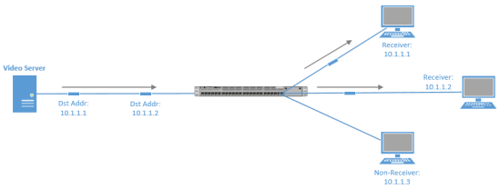
Most network traffic is unicast in nature, meaning that traffic travels specifically from a single source device to a single destination device. Below is an example of a unicast transmission. In IPv4 networks, unicast addresses are made up of Class A, B, and C addresses.
Note: IPv6 networks instead use global unicast addresses, which begin with the 2000::/3 prefix.
Broadcast
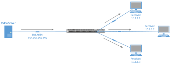
traffic travels from a single source to all destinations in a subnet (broadcast domain). A broadcast address of 255.255.255.255 might seem that it would reach all hosts on an interconnected network. However, 255.255.255.255 targets all devices on a single network, specifically the network local to the device sending a packet destined for 255.255.255.255. Another type of broadcast address is a directed broadcast address, which targets all devices in a remote network. The address 172.16.255.255 /16 is a directed broadcast targeting all devices in the 172.16.0.0 /16 network. Below is an example of a broadcast transmission.
Multicast
Multicast provides an efficient mechanism for a single host to send traffic to multiple, yet specific, destinations (pre-selected a group of hosts). Imagine a network with 100 users. Twenty of those users want to receive a video stream from a video server. With a unicast solution, the video server would have to send 20 individual streams, one stream for each recipient. This solution could consume a huge amount of network bandwidth and put a heavy load on the processor of the video server.
With a broadcast, the video server would only have to send the video stream once, but the stream would be received by every device on the segment, even devices not wanting to receive it.
Multicast offers a solution allowing the video server to send the video stream only once, and only sending the video stream to devices on the network that are suppose to receive that stream.
What enables this in IPv4 networks is the use of a Class D address:
Leading bits - 1110 = 224
224.0.0.0 - 239.255.255.255
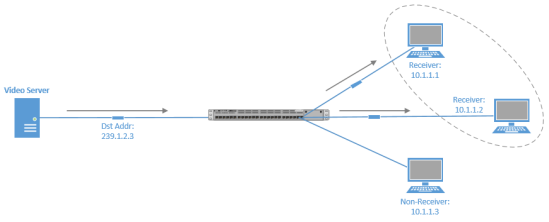
A Class D address, such as 239.1.2.3, represents the address of a multicast group.
The video server could send a single copy of each video stream packet destined for 239.1.2.3. Devices wanting to receive the video stream can join the multicast group.
Based on the device request, switches and routers in the topology can then dynamically determine out of which ports the video stream should be forwarded.
Note:In IPv6, multicast addresses have a prefix of FF00::/8.
TCP Out-of-Order Packets
In many routed environments, a router has more than one egress interface that can reach
a destination IP address. If load balancing is enabled in such a scenario, some packets in a traffic flow might go out one interface, while other packets go out of another interface.
With traffic flowing out of multiple interfaces, there is a chance that the packets will arrive out of order. Fortunately, TCP can help prevent out-of-order packets by either
sequencing them in the correct order or by requesting the retransmission of out-of-order
packets.
Cisco IOS Firewall and IPS track packets in TCP connections. If configured to look into the application data of the packets, Cisco IOS Firewall and IPS expect the TCP packets to arrive in the correct order because some data items are split across segments. When packets arrive out of order, they are dropped by the firewall or IPS. Dropping out-of-order packets can cause significant delays in end applications because packets are dropped only after the retransmission timer expires (on behalf of the sender).
Out-of-order TCP packet support enables IOS Firewall and IPS to hold a copy of the out-of-order packet in a buffer (size is configurable with a maximum of 1024 packets per session). The original packet passes through the router and reaches its destination, but the firewall or IPS do not execute on the packet. When the next packet arrives, the firewall or IPS look for that packet to “fill the hole,” providing a consecutive sequence of segments. If this packet does not fulfill that requirement, it is processed as an out-of-order packet, when another packet arrives and provides a consecutive sequence of segments, it is processed by the firewall or IPS.
Configure Cisco Router/Firewall/IPS to Handle TCP Out-of-Order Packets
Change any of the predefined parameters that instruct Cisco device application inspection or Cisco IOS IPS how to handle out-of-order TCP packets.
Router(config)# ip inspect tcp reassembly queue length 18
Router(config)# ip inspect tcp reassembly memory limit 200
Verify the configured out-of-order packet parameters
Router# show ip ips statistics

Signature Statistics [process switch:fast switch]
 Signature 1000: 324 packets checked: [124:200]
 Signature 1024: 100 packets checked: [0:100]
 Interfaces configured for ips 0
 Session creations since subsystem startup or last reset 0
 Current session counts (estab/half-open/terminating) [0:0:0]
 Maxever session counts (estab/half-open/terminating) [0:0:0]
 Last session created never
 Last statistic reset never
 TCP reassembly statistics
 received 200 packets out-of-order; dropped 25
 peak memory usage; 200 KB; current usage: 154 KB
 peak queue length 18
Asymmetric Routing
Many times, routing operations are impacted by Layer 2 switching in a network. Consider a situation, as shown below, where a VLAN is spread across multiple access layer switches, and a FHRP (HSRP, VRRP, or GLBP) is being used on multilayer switches at the distribution layer.
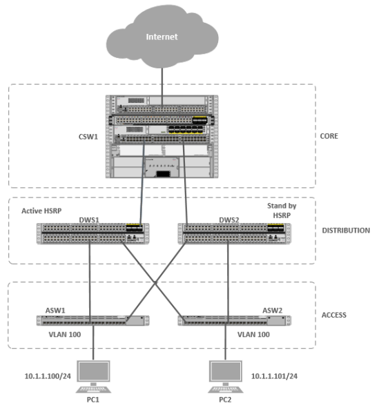
Notice that VLAN 100 exists on both switches ASW1 and ASW2 at the access layer. Also, notice that there are two multilayer switches at the distribution layer with an HSRP configuration to provide gateway redundancy to hosts in VLAN 100. The multilayer switch in the core layer supports equal-cost load balancing between DSW1 and DSW2.
Focusing on the HSRP configuration, imagine that DSW1 is the active router and DSW2 is the standby router. Next, imagine that PC1 sends traffic out to the Internet. The traffic flows through ASW1, DSW1 (the active HSRP router), and CSW1, as
shown below.

A challenge with this common scenario can occur with the return traffic, as shown above. The return traffic flows from the Internet and into CSW1, which then loadbalances between DSW1 and DSW2. When the path through DSW1 is used, the MAC address of PC1 is known to DSW1’s ARP cache (it just saw PC1’s MAC address being used as the source MAC address in a packet going out to the Internet). When the path through DSW2 is used, DSW2 might not have PC1’s MAC address in its ARP cache because PC1 isn’t normally using DSW2 as its default gateway. As a result, DSW2 floods this unknown unicast traffic out all its other ports.
This issue is known as Asymmetric Routing, because traffic might leave through one path (through DSW1) and return through a different path (through DSW2). Another name given to this issue is Unicast Flooding, because of the potential for a backup FHRP router or multilayer switch to flood unknown unicast traffic for returning traffic.

The recommended design approach is that you do not span a VLAN across more than one access layer switch to avoid such an issue. If a particular design requires the spanning of a VLAN across multiple access layer switches, the best practice (according to Cisco), is that you adjust the FHRP device’s ARP timer to be equal to or less than the Content Addressable Memory (CAM) aging time, or the CAM table entry for the end station will time out before the ARP entry times out, meaning that the FHRP device knows (from its ARP cache) the MAC address corresponding to the destination IP address, and does not need to ARP for the MAC address.
If the CAM entry has timed out, the FHRP device needs to flood the traffic to make sure that it gets to the intended destination. With an ARP timer equal to or less than the CAM aging time, there will never be an ARP entry for a MAC address not also stored in the CAM
table. As a result, if the FHRP device’s ARP entry has timed out, it will use ARP to get the MAC address of the destination IP address, thus causing the CAM table to learn the
appropriate egress port.
Hope this helps someone else!

Pingback: CCNP ROUTE 300-101 Part 3.0 – Layer 3 Technologies | ethernuno
Could you please continue your tuition. Excellence explaination
LikeLike
Could you please continue your tuition. Excellent explanation
LikeLike
Ashley, thanks. I’ll continue soon!
LikeLike
I’ll second this; your explanation and format are fantastic! Thank you so much for the work you’ve done so far. I really hope you have the time to finish the remaining topics for 300-101!
LikeLike
I have just cleared my exam 300-115 and have started preparing 300-101. It is amazing how simple you made the subjects. Thank you so much. I really appreciate.
LikeLike
This is super helpful thanks bud.
LikeLike
Late to the show, but still very precise information and excellent material to assist with 300-101 preparation!
LikeLike